background image

82

Using the setup menus

Use the setup menus to change the settings to 
suit the scenes you are shooting or what you are 
recording.

Operation 

lever

MENU button

MENU

PUSH-ENTER

AUDIO MON/ADV

EXEC

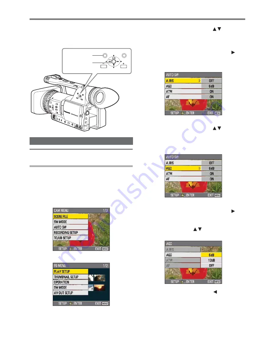
Using the menus

The menu items indicated in the gray 
characters cannot be changed its settings.

1

  When the unit is in other than playback or 

recording mode, press the MENU button.

The following is displayed on the viewfinder and 
LCD monitor.

CAM mode (Example)

PB mode (Example)

2

  Tilt the Operation lever in the     directions 

to move the yellow cursor to the function 
you wish to set.

3

  Push the Operation lever (or tilt in the   

direction) to display the setting items.

Example:

4

  Tilt the Operation lever in the     directions 

to move the yellow cursor to the item you 
wish to set.

Example:

5

  Push the Operation lever (or tilt in the   

direction) to set the item. 

To change values or other parameters, tilt the 
Operation lever in the     directions.

Example:

Tilt the Operation lever in the   direction to 
return to the previous menu.

6

 Repeat steps

 4 - 5 

to change any other 

items.

Press the MENU button to complete settings 
and return to the normal screen.

Summary of Contents for AG-HMC150

Page 1: ...Panasonic Broadcast AG HMC150 Menu Information...

Page 2: ...Example 2 Tilt the Operation lever in the directions to move the yellow cursor to the function you wish to set 3 Push the Operation lever or tilt in the direction to display the setting items Example...

Page 3: ...E screen The current menu settings of user file will return to the factory settings To initialize the scene file From the 6 scene files select the one you want to initialize with the scene dial Then i...

Page 4: ...DE MIC ALC Page 92 TCG MIC GAIN1 TC PRESET MIC GAIN2 UB PRESET EXT TC LINK AV OUT SETUP HDMI OUT SEL Page 93 CMPNT OUT SEL DOWNCON MODE DISPLAY SETUP ZEBRA DETECT1 VIDEO SETUP Page 94 ZEBRA DETECT2 AU...

Page 5: ...ER1 Page 88 USER2 USER3 LCD AV OUT SETUP HDMI OUT SEL Page 93 CMPNT OUT SEL DOWNCON MODE VIDEO SETUP AUDIO OUT DISPLAY SETUP VIDEO OUT OSD Page 94 DATE TIME LEVEL METER CARD BATTERY OTHER DISPLAY LCD...

Page 6: ...a faster rate 60P 60i 1 60 0 1 249 8 Factory default setting is 1 48 0 30P 1 30 0 1 48 0 1 249 8 24P 1 24 0 1 48 0 1 249 8 DETAIL LEVEL Camera Adjusts the level of the image outline correction in the...

Page 7: ...a designed to create cinema like images CINE LIKE V Uses a gamma designed to create cinema like images with emphasized contrast When you select CINE LIKE gamma we recommend setting the lens aperture l...

Page 8: ...dial is turned downward UP OPEN The iris opens when the IRIS dial is turned upward USER1 Camera PB Selects the function assigned to the USER1 button SPOTLIGHT Switches auto iris control for the spotli...

Page 9: ...ribution graph The frequency distribution graph is displayed on either the viewfinder or the LCD monitor WFM Camera Switches the waveform display that appears when the WFM button is pressed WAVE Displ...

Page 10: ...trol of the gain selected by the GAIN switch ATW Camera ON Performs the ATW Auto Tracing White Balance function in auto mode You cannot select ON OFF of the ATW function with the WHITE BAL switch or t...

Page 11: ...r recorded images ON Superimposes date and time information on the image OFF Does not superimpose date and time information on the image MIC ALC Camera Sets mic level auto control to ON or OFF Page 49...

Page 12: ...code is advanced only when recording TC PRESET Camera Sets the initial time code YES NO Set the frame value to 0 or a multiple of 4 when you set recording frame rate of recording format to 24P If any...

Page 13: ...ting from the VIDEO OUT terminal or when outputting from the COMPONENT OUT terminal when the COMPNT OUT SEL item is set to 480i LETTER BOX Adds black bands at the top and bottom of the image to displa...

Page 14: ...he VIDEO OUT jack ON OFF DATE TIME Camera PB Sets whether to display the date and time on the screen and whether to output from the VIDEO OUT jack TIME The time is displayed DATE The date is displayed...

Page 15: ...t shooting Selecting MIRROR displays the left and right side of the LCD monitor image inverted during self portrait shooting Page 41 NORMAL MIRROR EVF COLOR Camera PB Switches viewfinder images to col...

Page 16: ...to the last screen After a LOAD or INITIALIZE operation turn the POWER switch off and then back on again to make the new settings available The INITIALIZE operations do not change the TIME ZONE settin...

Page 17: ...P Stops playback at the beginning of the previous clip CLIP INDEX Stops at the beginning of the clip and INDEX THUMBNAIL SETUP screen Item Display mode Description of settings THUMBNAIL MODE PB Select...

Page 18: ...n if they are protected OTHER FUNCTIONS screen Item Display mode Description of settings IR REMOTE Camera PB Sets the operations of the supplied remote control unit ON Accepts commands from the remote...

Page 19: ...mbai 06 00 Dacca 04 30 Kabul 05 00 Islamabad 03 30 Tehran 04 00 Abu Dhabi 02 30 03 00 Moscow 01 30 02 00 Eastern Europe 00 30 01 00 Central Europe POWER SAVE Camera Selects the power saving mode when...

Reviews: