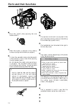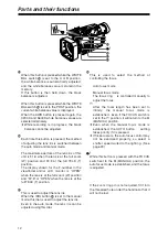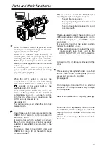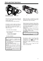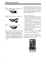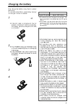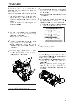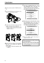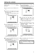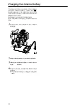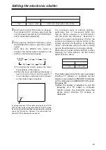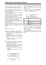
o
COUNTER RESET button
This button is used to reset the counter value
on the counter display and the memory
counter value to zero.
It cannot reset the time code or user’s bit.
p
COUNTER button
This button is used to select what data is to
be displayed on the counter display which is
in the viewfinder and on the LCD monitor.
Each time it is pressed, the data to be
displayed changes.
COUNTER:
The counter value is displayed.
M COUNTER:
The counter value in the memory stop
mode is displayed.
TC :
The time code is displayed.
UB :
The user’s bit is displayed.
Blank display :
No data is displayed.
q
MODE CHK button
When this button is pressed, the current
camera status setting can be checked in the
viewfinder and on the LCD monitor.
r
ZEBRA button
When this button is pressed in camera mode,
a zebra pattern appears in the viewfinder and
on the LCD monitor, enabling the brightness
of the subject to be checked.
When it is pressed again, a zebra pattern is
disappeared.
The level of zebra pattern can be set using
the ZEBRA DETECT item on the setting
menu DISPLAY SETUP screen.
(See page 43)
s
OIS button
This button is used to set camera shake
compensation to ON or OFF. When the
compensation is ON,
appears in the
viewfinder and on the LCD monitor.
Select ON or OFF to suit the shooting
conditions.
When shooting using a tripod, the OFF
setting is recommended.
t
Tripod mounting hole
Zebra pattern
Parts that may be whitened out due to overexposure
are displayed using a striped pattern.
s
o
p
q
r
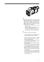
Memory stop mode
The memory stop mode is established when the
display is switched to M COUNTER using the
COUNTER button.
1
Switch the display to M COUNTER, and press the
COUNTER RESET button
o
at any tape position to
reset the counter value.
2
Proceed with playback or shooting.
3
Establish the VCR mode using the CAMERA/VCR
button.
4
When the tape is now rewound or fast forwarded, it
stops traveling automatically near where the counter
value was reset.
O
If the counter value is reset at the OUT point during
audio dubbing, audio dubbing can be stopped in the
memory stop mode.
17
Parts and their functions
t
Summary of Contents for AG-DVC80P
Page 24: ...24 ...
Page 61: ...Memo ...

