


Reviews:
No comments
Related manuals for AG-7330
Omnivision PV-9661
Brand: Panasonic Pages: 407
NV-P05REE
Brand: Panasonic Pages: 11
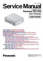
NV-P05REE
Brand: Panasonic Pages: 52
AJ-YA120AG
Brand: Panasonic Pages: 56
OmniVision PV-QV200
Brand: Panasonic Pages: 34

DVST1C1WX-BG/D
Brand: Daewoo Pages: 47

DDV9150
Brand: Sensory Science Pages: 106

3919CLC
Brand: Sylvania Pages: 64

AG-A850
Brand: Panasonic Pages: 4

MGTD204
Brand: Magnavox Pages: 104

F319CA
Brand: FUNAI Pages: 48

Omnivision PV-M2048-K
Brand: Panasonic Pages: 39

NV-HD635
Brand: Panasonic Pages: 101

NV-HD660 EC
Brand: Panasonic Pages: 129

NV-HD630A
Brand: Panasonic Pages: 103

NV-HD670 Series
Brand: Panasonic Pages: 40

NV-HD630 series
Brand: Panasonic Pages: 40

NV-HD650 Series
Brand: Panasonic Pages: 37


