


25
PICTURE Adjustments
ADVANCED SETTINGS
Notes:
• “COLOR” and “TINT” settings cannot be
adjusted for “RGB/PC” and “Digital” input
signal.
• You can change the level of each function
(PICTURE, BRIGHTNESS, COLOR, TINT,
SHARPNESS) for each PICTURE MENU.
• The “TINT” setting can be adjusted
for NTSC signal only during “VIDEO
(S VIDEO)” input signal.
• In PICTURE, there is not a noticeable
change even when contrast is increased
with a bright picture or reduced with a dark
picture.
On the remote control unit, while the “ADVANCED SETTINGS” menu is displayed, if either the N button is pressed at
any time or the ACTION ( ) button is pressed during “NORMALIZE”, then all adjustment values are returned to the
factory settings.
Helpful Hint ( /
NORMALIZE
Normalization)
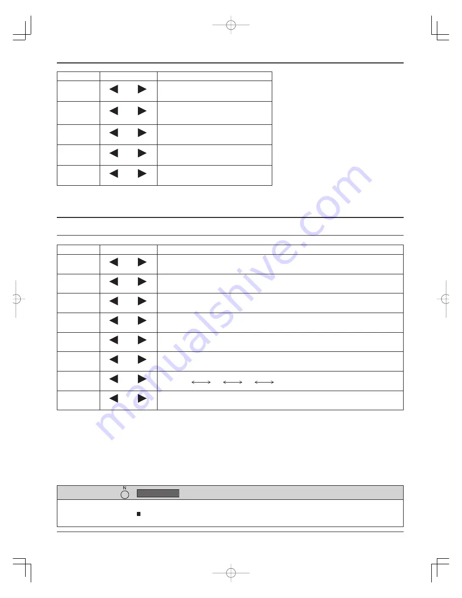
Item
Effect Adjustments
PICTURE
Less
More
Adjusts the proper picture contrast.
BRIGHTNESS
Darker
Brighter
Adjusts for easier viewing of dark
pictures such as night scenes and
black hair.
COLOR
Less
More
Adjusts color saturation.
TINT
Reddish
Greenish
Adjusts for natural
fl
esh tones.
SHARPNESS
Less
More
Adjusts picture sharpness.
Item
Effect Details
BLACK
EXTENSION
Less
More
Adjusts the dark shades of the image in gradation.
INPUT
LEVEL
Less
More
Adjustment of parts which are extremely bright and hard to see.
(This cannot be adjusted when the input signal is Digital.)
W/B HIGH R
Less
More
Adjusts the white balance for light red areas.
W/B HIGH B
Less
More
Adjusts the white balance for light blue areas.
W/B LOW R
Less
More
Adjusts the white balance for dark red areas.
W/B LOW B
Less
More
Adjusts the white balance for dark blue areas.
GAMMA
Down
Up
S CURVE
2.0
2.2
2.5
AGC
OFF
ON
Increases the brightness of dark signal automatically.
Notes:
• Carry out “W/B” adjustment as follows.
1.
Adjust the white balance of the bright sections using the “W/B HIGH R” and “W/B HIGH B” settings.
2.
Adjust the white balance of the dark sections using the “W/B LOW R” and “W/B LOW B” settings.
3.
Repeat steps
1
and
2
to adjust.
Steps
1
and
2
affect each other’s settings, so repeat each step in turn to make the adjustment.
• The adjustment values are memorized separately for each input terminal.
• The adjustment range values should be used as an adjustment reference.
th̲65pf9uk̲Eng̲721.indb 25
th̲65pf9uk̲Eng̲721.indb 25
2006/08/03 16:52:37
2006/08/03 16:52:37


