Panasonic 42PH9UK - TH - 42

34

SET UP for MULTI DISPLAY

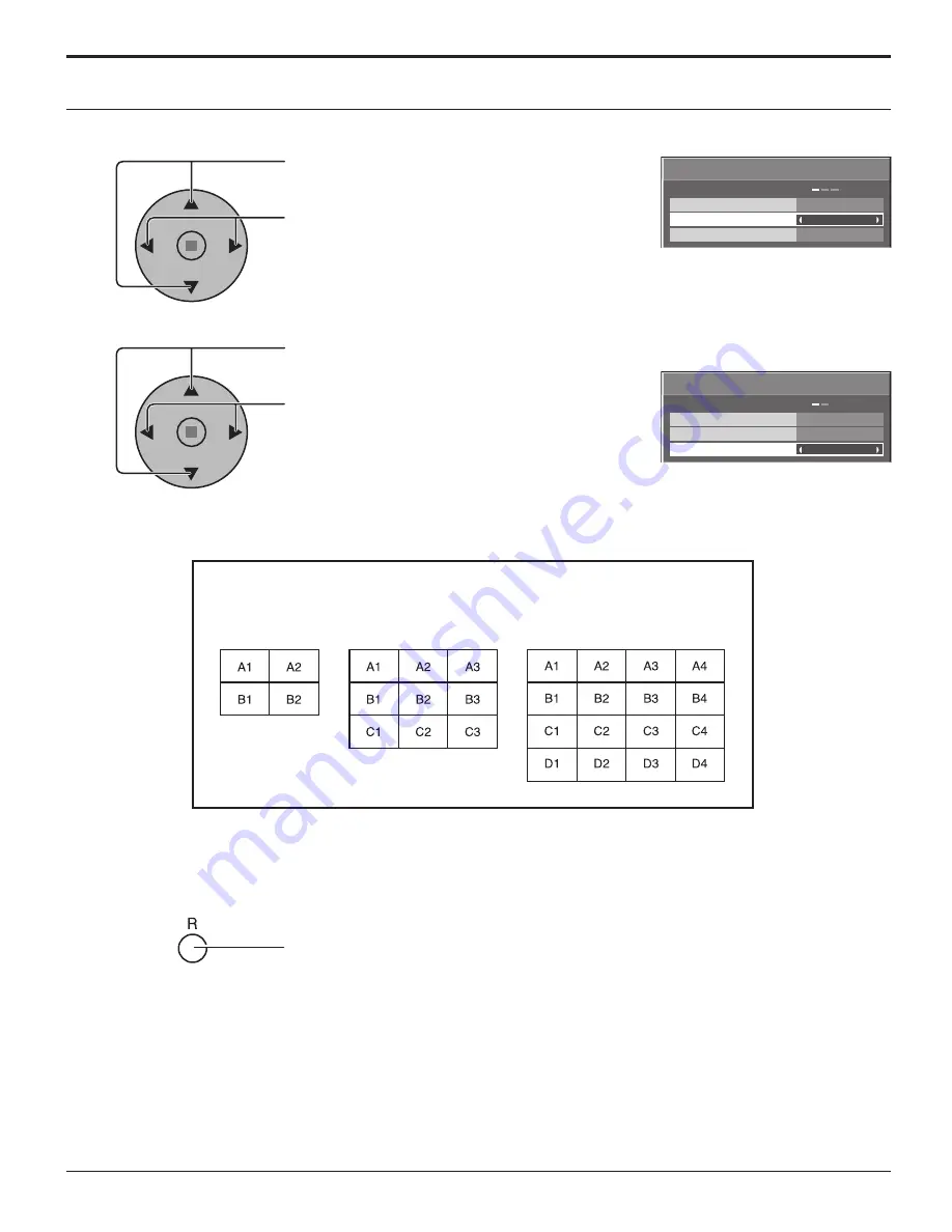
Press to select ARRANGEMENT (2nd step).

Press to select “2 × 2”, “2 × 2F”, “3 × 3”, “3 × 3F”, 
“4 × 4”, “4 × 4F”.

Press to select LOCATION.

Press to select the required arrangement number. 
(A1-D4 : Refer to the following)

How to set the Display location number for each Plasma Display 

Display Number locations for each arrangement.

Press twice to exit from SET UP.

4

5

LOCATION

MULTI DISPLAY SETUP
ARRANGEMENT

OFF

2 × 2

A1

MULTI DISPLAY SETUP

2 × 2

A1

LOCATION

MULTI DISPLAY SETUP
ARRANGEMENT

OFF

MULTI DISPLAY SETUP

( 2 × 2 (F) )

( 3 × 3 (F) )

( 4 × 4 (F) )

6

Summary of Contents for 42PH9UK - TH - 42" Plasma Panel

Page 1: ...s manual for future reference La ilustración mostrada es una imagen Antes de conectar utilizar o ajustar este producto lea completamente este manual de instrucciones y guárdelo para consultarlo en el futuro en caso de ser necesario Español Operating Instructions Progressive Wide Plasma Display Manual de instrucciones Pantalla panorámica de plasma progresiva TH 42PS9UK TH 37PH9UK TH 42PH9UK TH 50PH...

Page 2: ...DO NOT OPEN WARNING To prevent damage which may result in fire or shock hazard do not expose this apparatus to rain or moisture Do not place containers with water flower vase cups cosmetics etc above the set including on shelves above etc WARNING 1 To prevent electric shock do not remove cover No user serviceable parts inside Refer servicing to qualified service personnel 2 Do not remove the groun...

Page 3: ...ent of the obsolete outlet 10 Protect the power cord from being walked on or pinched particularly at plugs convenience receptacles and the point where they exit from the apparatus 11 Only use attachments accessories specified by the manufacturer 12 Use only with the cart stand tripod bracket or table specified by the manufacturer or sold with the apparatus When a cart is used use caution when movi...

Page 4: ...ing the On Screen Menu Language 18 ASPECT Controls 19 Adjusting POS SIZE 20 MULTI PIP 21 Advanced PIP 22 PICTURE Adjustments 23 ADVANCED SETTINGS 24 SOUND Adjustment 25 MUTE 25 Digital Zoom 26 PRESENT TIME SETUP SET UP TIMER 27 PRESENT TIME SETUP 27 SET UP TIMER 28 SCREENSAVER For preventing after images 29 Setup of SCREENSAVER Time 30 Reduces screen after image 30 SIDE BAR ADJUST 31 Reduces power...

Page 5: ...harmful interference and 2 this device must accept any interference received including interference that may cause undesired operation FCC CAUTION Pursuant to 47CFR Part 15 21 of the FCC rules any changes or modifications to this monitor not expressly approved by Panasonic Corporation of North America could cause harmful interference and would void the user s authority to operate this device FCC D...

Page 6: ...c bags sheets to prevent them from being played with by young children creating the potential risk of suffocation CAUTION When using the Plasma Display Do not bring your hands face or objects close to the ventilation holes of the Plasma Display Top of the Plasma Display is usually very hot due to the high temperature of exhaust air being released through the ventilation holes Burns or personal inj...

Page 7: ...ilation holes Doing so may cause the Plasma Display to overheat which can cause fire or damage to the Plasma Display If using the pedestal optional accessory leave a space of 3 15 16 10 cm or more at the top left and right 2 3 8 6 cm or more at the bottom and 2 3 4 7 cm or more at the rear If using some other setting up method leave a space of 3 15 16 10 cm or more at the top bottom left and right...

Page 8: ...mix battery types example Zinc Carbon with Alkaline 4 Do not attempt to charge short circuit disassemble heat or burn used batteries 5 Battery replacement is necessary when the remote control acts sporadically or stops operating the Plasma Display 3 Replace the cover Accessories Supplied Check that you have the Accessories and items shown Operating Instruction book Remote Control Transmitter EUR76...

Page 9: ...e is sufficient slack in cables to minimize stress especially in the power cord firmly bind all cables with the supplied fixing band From SERIAL Terminal on Computer see page 11 From EXTERNAL monitor terminal on Computer see page 10 AC cord connection see page 13 Dual Video Terminals see page 12 To tighten To loosen Pull Pull Push the catch 3 Slide up the clamper and fix the AC cord plug securely ...

Page 10: ...ted is not DDC1 2B compatible you will need to make setting changes to the computer at the time of connection Some PC models cannot be connected to the set There is no need to use an adapter for computers with DOS V compatible Mini D sub 15P terminal The computer shown in the illustration is for example purposes only Additional equipment and cables shown are not supplied with this set Do not set t...

Page 11: ...re are no parameters then the parameter signal does not need to be sent Notes If multiple commands are transmitted be sure to wait for the response for the first command to come from this unit before sending the next command If an incorrect command is sent by mistake this unit will send an ER401 command back to the computer With the power off this display responds to PON command only 9 8 7 6 5 3 2...

Page 12: ... A DVD Computer RGB Camcorder or Notes Change the COMPONENT RGB IN SELECT setting in the SET UP menu to COMPONENT see page 38 Additional equipment cables and adapter plugs shown are not supplied with this set Notes Change the COMPONENT RGB IN SELECT setting in the SET UP menu to RGB see page 38 Additional equipment cables and adapter plugs shown are not supplied with this set S VIDEO VCR CAMCORDER...

Page 13: ... On Power Indicator Green Example The screen below is displayed for a while after the Plasma Display is turned on setting condition is an example Connecting the AC cord plug to the Plasma Display Fix the AC cord plug securely to the Plasma Display with the clamper see page 9 TH 42PS9 INPUT MENU ENTER VOL TH 42PWD8 Power Indicator Remote Control Sensor Press the button on the remote control to turn...

Page 14: ...he cursor down see page 16 Enter Aspect button see page 16 19 Normal Viewing PICTURE SET UP SOUND POS SIZE Basic Controls Remote control sensor N button see page 20 23 24 25 POS SIZE button see page 20 PICTURE button see page 23 INPUT button INPUT1 INPUT2 INPUT3 and PC IN selection Press to select INPUT1 INPUT2 INPUT3 and PC IN input SLOTS sequentially see page 18 Sound mute On Off see page 25 Num...

Page 15: ...this function is not the perfect solution to after image Channel Adjustment This button cannot be used for this model Volume Adjustment Press the Volume Up or Down button to increase or decrease the sound volume level OFF TIMER button The Plasma Display can be preset to switch to stand by after a fixed period The setting changes to 30 minutes 60 minutes 90 minutes and 0 minutes off timer cancelled...

Page 16: ...ER SAVE SET UP 2 2 SET UP SCREENSAVER MULTI DISPLAY SETUP SET UP TIMER PRESENT TIME SETUP from the unit 1 Press to select INPUT MENU ENTER VOL 1 2 PICTURE NORMAL NORMALIZE STANDARD 25 0 0 0 3 BRIGHTNESS SHARPNESS PICTURE MENU COLOR PICTURE TINT 2 2 ADVANCED SETTINGS COLOR TEMP COLOR MANAGEMENT NORMAL OFF ON PICTURE 1 Press to select 2 Press to access each adjust screen INPUT MENU ENTER VOL 1 2 To ...

Page 17: ...0 00 0 00 SET UP TIMER POWER OFF FUNCTION POWER OFF TIME POWER ON TIME POWER ON FUNCTION OFF OFF PRESENT TIME OF DAY 99 99 Press the R button to return to SET UP menu Press to select START TIME FINISH TIME When TIME OF DAY is selected Press to select SHOW DURATION SAVER DURATION When INTERVAL is selected Press to set up To setup SCREENSAVER See page 29 31 To setup MULTIDISPLAY screen See page 33 I...

Page 18: ...ack from the equipment which has been connected to the Plasma Display Input signals will change as follows TH 37PH9UK TH 42PS9UK TH 42PH9UK TH 50PH9UK Notes Selecting is also possible by pressing the INPUT button on the unit Input terminal will not be selected if the terminal board is not installed into the SLOT Select to match the signals from the source connected to the component RGB input termi...

Page 19: ...O Panasonic AUTO 4 16 3 9 The display will automatically become enlarged depending on the picture source allowing you to view the picture at its maximum size Notes Panasonic AUTO mode is designed to automatically adjust the aspect ratio to handle a mix of 16 9 and 4 3 program material Certain 4 3 program material such as stock market data screens may occasionally cause the image size to change une...

Page 20: ...om a VCR or DVD player is received the picture position will shift up or down This picture position movement cannot be controlled by the POS SIZE function If adjusting the PICTURE V POS V SIZE in Panasonic AUTO with FULL mode the adjustment is not memorized When exiting the mode the screen will return to a former adjustment While the POS SIZE display is active if either the N button on the remote ...

Page 21: ...the picture which is selected in Audio OUT PIP See page 25 In 2 screen display the same input mode cannot be selected for the main picture and sub picture The main picture and sub picture are processed by different circuits resulting in a slight difference in the clarity of the pictures There may also be a difference in the picture quality of the sub picture depending on the type of signals displa...

Page 22: ...cture depending on the type of signals displayed on the main picture and depending on the 2 picture display mode Due to the small dimensions of the sub pictures these sub pictures cannot be shown in detail Computer screen picture is displayed in a simplified format and it may not be possible to discern details on them satisfactorily Following combinations of two analog signals cannot be displayed ...

Page 23: ...NCED SETTINGS ON Enables fine picture adjustment at a professional level see next page ADVANCED SETTINGS OFF Displays images with settings of the PICTURE menu Press to enter Advanced Settings 0 0 0 0 0 0 2 2 W B LOW B BLACK EXTENSION W B HIGH B W B LOW R AGC GAMMA INPUT LEVEL W B HIGH R ADVANCED SETTINGS NORMAL NORMALIZE OFF COLOR MANAGEMENT ON Enables vivid color adjustment automatically Press th...

Page 24: ...More Adjusts color saturation TINT Reddish Greenish Adjusts for natural flesh tones SHARPNESS Less More Adjusts picture sharpness Item Effect Details BLACK EXTENSION Less More Adjusts the dark shades of the image in gradation INPUT LEVEL Less More Adjustment of parts which are extremely bright and hard to see This cannot be adjusted when the input signal is DVI W B HIGH R Less More Adjusts the whi...

Page 25: ...t each item Useful when answering the phone or receiving unexpected visitors Press this button to mute the sound Press again to reactivate sound Sound is also reactivated when power is turned off or volume level is changed While the SOUND menu is displayed if either the N button on the remote control is pressed at any time or the ACTION button is pressed during NORMALIZE then all adjustment values...

Page 26: ...wer Picture in Picture Picture out Picture Picture and Picture operation see page 21 While Digital Zoom is in operation Adjusting POS SIZE cannot be used Select the magnification required for the enlarged display Each time this is pressed the magnification factor changes This is shown in the image being displayed 3 2 4 The cursor will move 2 EXIT 1 1 EXIT 1 Display the Operation Guide Press to acc...

Page 27: ...up PRESENT TIME OF DAY button Forward button Back Notes Pressing or button once changes PRESENT TIME OF DAY 1minute Pressing or button continuously changes PRESENT TIME OF DAY by 15 minutes Press to select Set Press to store PRESENT TIME SETUP Note Set cannot be selected unless PRESENT TIME OF DAY is set Press to exit from PRESENT TIME SETUP 1 2 1 2 PC OFF STANDBY SAVE OFF POWER MANAGEMENT OFF AUT...

Page 28: ... TIME POWER OFF TIME by 15 minutes Press to select POWER ON FUNCTION POWER OFF FUNCTION Press to select ON Press twice to exit from SET UP Note Timer function will not work unless PRESENT TIME OF DAY is set Display the SET UP TIMER SCREEN 1 2 3 0 00 0 00 SET UP TIMER POWER OFF FUNCTION POWER OFF TIME POWER ON TIME POWER ON FUNCTION OFF OFF PRESENT TIME OF DAY 99 99 0 00 0 00 SET UP TIMER POWER OFF...

Page 29: ...ton Press to select the MODE Press to select each mode items OFF INTERVAL Operates when SHOW DURATION and SAVER DURATION are set up and those times arrive TIME OF DAY Operates when START TIME and FINISH TIME are set up and those times arrive ON Operates when START is selected and the ACTION button is pressed SCREENSAVER For preventing after images 2 2 SET UP SCREENSAVER MULTI DISPLAY SETUP SET UP ...

Page 30: ... 3 1 Press to display the SET UP menu SCREENSAVER For preventing after images SCREENSAVER START FUNCTION MODE WOBBLING PEAK LIMIT FINISH TIME START TIME WHITE BAR SCROLL OFF 6 15 12 30 OFF OFF SIDE BAR ADJUST BRIGHT PRESENT TIME OF DAY 99 99 SCREENSAVER START FUNCTION MODE WOBBLING PEAK LIMIT WHITE BAR SCROLL 6 15 12 30 OFF OFF INTERVAL SIDE BAR ADJUST BRIGHT SAVER DURATION SHOW DURATION PRESENT T...

Page 31: ...operation guide steps 1 and 2 Notes To reduce the occurrence of after images set the SIDE BAR ADJUST to BRIGHT The side bar may flash alternate black white depending on the picture being shown on the screen Using Cinema mode will reduce such flashing side bars NORMAL mode after images A B Picture out Picture Picture and Picture Non picture area This function may be applicable to the non picture ar...

Page 32: ...Customizing the Input labels This function can change the label of the Input signal to be displayed Note While selecting a Input signal through Optional Terminal Board connected to Slot 1 Slot 2 and Slot 3 the Input label will depend on each Optional Terminal Board INPUT LABELS for Slot 1 Slot 2 Slot 3 and miniD sub Slot1 Input INPUT1 VIDEO1 COMPONENT1 RGB1 DIGITAL1 PC1 DVD1 CATV1 VCR1 STB1 Slot2 ...

Page 33: ...ation Press to display the SET UP menu Press to select the MULTI DISPLAY SETUP Press to display the MULTI DISPLAY SETUP menu Press to select the MULTI DISPLAY SETUP Press to select ON or OFF How to setup MULTI DISPLAY group of 16 4 4 F group of 4 2 2 F group of 9 3 3 F 1 2 3 2 2 SET UP SCREENSAVER MULTI DISPLAY SETUP SET UP TIMER PRESENT TIME SETUP 2 2 A1 LOCATION MULTI DISPLAY SETUP ARRANGEMENT O...

Page 34: ...red arrangement number A1 D4 Refer to the following How to set the Display location number for each Plasma Display Display Number locations for each arrangement Press twice to exit from SET UP 4 5 LOCATION MULTI DISPLAY SETUP ARRANGEMENT OFF 2 2 A1 MULTI DISPLAY SETUP 2 2 A1 LOCATION MULTI DISPLAY SETUP ARRANGEMENT OFF MULTI DISPLAY SETUP 2 2 F 3 3 F 4 4 F 6 ...

Page 35: ...on Press to display the SET UP menu Press to select the MULTI DISPLAY SETUP Press to display the MULTI DISPLAY SETUP menu Press to select the MULTI DISPLAY SETUP Press to select ON or OFF How to setup MULTI DISPLAY group of 16 4 4 group of 4 2 2 group of 9 3 3 1 2 3 2 2 SET UP SCREENSAVER MULTI DISPLAY SETUP SET UP TIMER PRESENT TIME SETUP 2 MULTI DISPLAY SETUP HORIZONTAL SCALE OFF OFF A1 LOCATION...

Page 36: ...TAL SCALE VERTICAL SCALE SEAM HIDES VIDEO 2 2 2 1 2 3 4 4 8 Press to select HORIZONTAL SCALE Press to select 1 2 3 4 Press to select LOCATION Press to select the required arrangement number A1 D4 Refer to the following 2 MULTI DISPLAY SETUP HORIZONTAL SCALE OFF OFF A1 LOCATION VERTICAL SCALE SEAM HIDES VIDEO 2 MULTI DISPLAY SETUP 5 Press to select VERTICAL SCALE Press to select 1 2 3 4 6 Press to ...

Page 37: ...is has the same effect as pressing the buttons at the same time Notes Set the Remote ID On to operate the ID remote control If remote ID is set to On you can use the remote control without identical ID number during option menu display see page 43 The ID remote control cannot be used when ID select is set to anything other than 0 and the remote control ID is not the same as the ID select number se...

Page 38: ...ed Note When ON this setting only affects NTSC input signals Note Selection may not be possible depending on which optional board is installed 1 2 1 2 PC OFF STANDBY SAVE OFF POWER MANAGEMENT OFF AUTO POWER OFF OFF OSD LANGUAGE ENGLISH US COMPONENT RGB IN SELECT RGB INPUT LABEL SIGNAL POWER SAVE SET UP 1 2 PC OFF STANDBY SAVE OFF POWER MANAGEMENT OFF AUTO POWER OFF OFF OSD LANGUAGE ENGLISH US COMP...

Page 39: ...NR cannot be adjusted while a PC signal is being applied 1 2 Press ACTION button Mode Function COLOR SYSTEM Set the color system to match the input signal If set to AUTO the color system is determined automatically AUTO SECAM M NTSC NTSC PAL Panasonic AUTO 4 3 Set to NORMAL to view 4 3 images in an unchanged format when Panasonic AUTO is selected If you would like to view 4 3 images in Just format...

Page 40: ...ch is input from the G connector VBS Uses a synchronized signal of Composite Sync input which is input from the HD connector Displays the H Horizontal V Vertical frequencies This display is valid only for RGB PC and DVI input signal Display range Horizontal 15 110 kHz Vertical 48 120 Hz H FREQ kHz V FREQ Hz 1 2 PC OFF STANDBY SAVE OFF POWER MANAGEMENT OFF AUTO POWER OFF OFF OSD LANGUAGE ENGLISH US...

Page 41: ...Displays all the following on screen Power on display Input signal switch display No signal display Mute and the remaining time of off timer after was pressed Off Hides all the items above from view Initial INPUT Off PC INPUT1 INPUT2 INPUT3 Adjusts the input signal when TV is turned on Notes Only the adjusted signal is displayed see page 18 Signal can be displayed when the Terminal board is instal...

Page 42: ...ff In two screen display mode if anything other than Off is set the value will be fixed as the value input in the single screen display mode Studio W B Off On Off Nullify all the settings adjusted On Sets the color temperature for TV studio Note Valid only when the low is set as color temperature on screen adjustment Advanced PIP Off On Off Sets normal two screen display mode see page 21 On Sets A...

Page 43: ... is transmitted to the slot power when main power is on or in the standby state Note In some cases power is transmitted to the slot power when main power is on or in the standby state regardless of the slot power setting V Installation Off On Off Sets fan to the horizontal installation mode On Sets fan to the vertical installation mode Notes This functions when display is turned on This mode is av...

Page 44: ...ll the Setup menu is displayed 2 Press the Volume Up or Down button to select OSD LANGUAGE 3 Press and hold the ENTER button till the SHIPPING menu is displayed 4 Press the Volume Up or Down button to select YES 5 Press the ENTER button Note Press the R button to return to SET UP menu when SHIPPING menu is displayed 1 2 PC OFF STANDBY SAVE OFF POWER MANAGEMENT OFF AUTO POWER OFF OFF OSD LANGUAGE E...

Page 45: ...e and audio depending on the type of input signal However this is not a malfunction Plasma Display panel Symptoms Check The screen darkens slightly when bright pictures with minimal movements are shown The screen will darken slightly when photos still images of a computer or other pictures with minimal movements are shown for an extended period This is done to reduce after image on the screen and ...

Page 46: ...7 640 480 75 Hz 37 50 75 00 18 640 480 85 Hz 43 27 85 01 19 852 480 60 Hz 31 47 59 94 2 20 800 600 56 Hz 35 16 56 25 21 800 600 60 Hz 37 88 60 32 22 800 600 72 Hz 48 08 72 19 23 800 600 75 Hz 46 88 75 00 24 800 600 85 Hz 53 67 85 06 25 1 024 768 60 Hz 48 36 60 00 26 1 024 768 70 Hz 56 48 70 07 27 1 024 768 75 Hz 60 02 75 03 28 1 024 768 85 Hz 68 68 85 00 29 1 152 864 75 Hz 67 50 75 00 30 1 280 960...

Page 47: ...terminals AV VIDEO IN BNC 1 0 Vp p 75 Ω or high impedance S VIDEO IN MINI DIN 4PIN Y 1 Vp p 75 Ω C 0 286 Vp p 75 Ω AUDIO IN RCA PIN JACK 4 0 5 Vrms high impedance COMPONENT RGB Y G BNC 1 0 Vp p with sync 75 Ω 0 7 Vp p without sync 75 Ω PB B BNC PR R BNC 0 7 Vp p 75 Ω AUDIO IN RCA PIN JACK 2 0 5 Vrms high impedance PC HIGH DENSITY Mini D SUB 15PIN R G B 0 7 Vp p 75 Ω HD VD 1 0 5 0 Vp p high impedan...

Page 48: ...XGA SXGA UXGA compressed Horizontal scanning frequency 15 110 kHz Vertical scanning frequency 48 120 Hz Connection terminals AV VIDEO IN BNC 1 0 Vp p 75 Ω or high impedance S VIDEO IN MINI DIN 4PIN Y 1 Vp p 75 Ω C 0 286 Vp p 75 Ω AUDIO IN RCA PIN JACK 4 0 5 Vrms high impedance COMPONENT RGB Y G BNC 1 0 Vp p with sync 75 Ω 0 7 Vp p without sync 75 Ω PB B BNC PR R BNC 0 7 Vp p 75 Ω AUDIO IN RCA PIN ...

Page 49: ... terminals AV VIDEO IN BNC 1 0 Vp p 75 Ω or high impedance S VIDEO IN MINI DIN 4PIN Y 1 Vp p 75 Ω C 0 286 Vp p 75 Ω AUDIO IN RCA PIN JACK 4 0 5 Vrms high impedance COMPONENT RGB Y G BNC 1 0 Vp p with sync 75 Ω 0 7 Vp p without sync 75 Ω PB B BNC PR R BNC 0 7 Vp p 75 Ω AUDIO IN RCA PIN JACK 2 0 5 Vrms high impedance PC HIGH DENSITY Mini D SUB 15PIN R G B 0 7 Vp p 75 Ω HD VD 1 0 5 0 Vp p high impeda...

Page 50: ... products not supplied by the warrantor or failures which result installation set up adjustments improper antenna inadequate signal pickup maladjustment of consumer controls improper operation power line surge improper voltage supply lighting damage or service by anyone other than an authorized repair facility or damaged this attributable to acts of God LIMITS AND EXCLUSIONS There are no express w...

Page 51: ... performance of the product For products requiring routine preventive maintenance that maintenance must be performed in order to maintain warranty coverage Serial numbers that have been altered defaced or removed void this warranty This warranty does not cover replacements or repairs necessitated by loss or damage resulting from any cause beyond the control of PCI Marking or retained images someti...

Page 52: ...Para impedir los daños que podrían ser causados por una descarga eléctrica no exponga este aparato a la lluvia ni a la humedad No ponga recipientes con agua floreros tazas cosméticos etc encima del aparato incluyendo los estantes que estén encima de él etc ADVERTENCIA 1 Para impedir recibir descargas eléctricas no retire la cubierta En el interior no hay piezas que deba reparar el usuario Solicite...

Page 53: ... de alimentación para que no sea pisado ni pellizcado especialmente en las clavijas tomas de corriente y en el punto por donde sale del aparato 11 Utilice solamente los aditamentos accesorios que haya especificado el fabricante 12 Utilice el aparato sólo con el mueble con ruedas soporte trípode ménsula o mesa especificado por el fabricante o vendido con el aparato Cuando utilice un mueble con rued...

Page 54: ...IP avanzado 22 Ajuste de imagen 23 Ajustes avanzados 24 Ajuste del sonido 25 Silenciamiento 25 Zoom digital 26 Puesta de HORA ACTUAL TEMPORIZADOR ajuste 27 Puesta de HORA ACTUAL 27 TEMPORIZADOR ajuste 28 Protec pantalla Para impedir las imágenes secundarias 29 Establecimiento del tiempo de activación de Protec Pantalla 30 Reducción del efecto de imagen secundaria en la pantalla 30 Ajuste de panele...

Page 55: ...o no debe causar interferencias perjudiciales y 2 debe aceptar cualquier interferencia recibida incluyendo aquellas que puedan causar un funcionamiento no deseado AVISO DE LA FCC Cualquier cambio o modificación que se hiciera sin contar con la aprobación de Panasonic Corporation of North America podría causar interferencias perjudiciales y anularía la autorización que tiene el usuario para utiliza...

Page 56: ...e de los niños pequeños Tire las partes pequeñas y objetos incluyendo materiales para embalaje y bolsas papeles de plástico para que los niños pequeños no jueguen ya que si lo hicieran corren un riesgo potencial de sofocación Cuando utilice la pantalla de plasma No acerque sus manos rostro u otros objetos cerca de los orificios de ventilación de la pantalla de plasma El aire que sale de los orific...

Page 57: ...e excesivamente provocado fuego o daños en la Pantalla de plasma Si se utiliza un pedestal accesorio opcional deje un espacio de 3 15 16 10 cm o más en la parte superior izquierda y derecha 2 3 8 6 cm o más en la parte inferior y 2 3 4 7 cm o más en la parte posterior Si se utiliza algún otro método de instalación deje un espacio de 3 15 16 10 cm o más en la parte superior inferior izquierda y der...

Page 58: ...s de carbón de zinc con alcalinas 4 No intente cargar cortocircuitar desarmar calentar o quemar las pilas usadas 5 El reemplazo de las pilas es necesario cuando el mando a distancia funciona esporádicamente o no puede controlar la pantalla de plasma 3 Vuelva a colocar la tapa Accesorios suministrados Compruebe que ha recibido todos los accesorios indicados Manual de instrucciones Transmisor del ma...

Page 59: ...ecialmente el cable de la alimentación una firmemente todos los cables con la banda de fijación suministrada Del terminal serial de una computadora vea la página 11 Del terminal de salida del monitor de una computadora vea la página 10 Conexión del cable de alimentación de CA vea la página 13 Terminales de vídeo dual vea la página 12 Para apretar Para aflojar Tire Tire Empuje la perilla 3 Deslice ...

Page 60: ...C1 2B necesitará hacer los cambios de ajuste en el momento de la conexión Algunos modelos de PC no pueden conectarse a la pantalla de plasma No es necesario un adaptador para con terminal mini D sub 15 patillas compatibles con DOS V Esta figura es sólo a modo de ejemplo Los equipos y cables adicionales de la figura no se suministran con este equipo No ajuste las frecuencias de exploración horizont...

Page 61: ...raciones de control Cumple con RS 232C Asincrónico 9600 bps Ninguna 8 bits 1 bit 2 3 4 5 6 7 8 9 1 Cable de conversión RS 232C Hembra de 9 patillas D sub Detalles R X D T X D GND No se usa Cortocircuitado NC Formato básico para datos de control La transmisión de los datos de control del ordenador empieza con la señal STX seguida por el comando los parámetros y por último una señal ETX en ese orden...

Page 62: ...leccione entrada componente RGB en el menú Configuración a Componente vea la página 38 El equipo adicional los cables y los enchufes de adaptador no se suministran con este aparato Notas Cambie el ajuste Seleccione entrada componente RGB en el menú Configuración a RGB vea la página 38 El equipo adicional los cables y los enchufes de adaptador no se suministran con este aparato VIDEOGRABADORA S VID...

Page 63: ... de abajo se mostrará durante un rato después de encendida la pantalla de plasma La condición del ajuste es un ejemplo Conexión de la clavija del cable de alimentación de CA a la pantalla de plasma Fije firmemente la clavija del cable de alimentación de CA en la pantalla de plasma con el fijador vea la página 9 TH 42PS9 INPUT MENU ENTER VOL TH 42PWD8 Indicador de alimentación Sensor del mando a di...

Page 64: ... página 23 Tecla INPUT Selección de INPUT1 INPUT2 INPUT3 y PC IN Pulseparaseleccionarsecuencialmentelasranurasdeentrada INPUT1 INPUT2 INPUT3 y PC IN vea la página18 Silenciamiento de sonido vea la página 25 Teclas numéricas vea la página 37 43 Tecla ASPECT Presione para ajustar el aspecto vea la página 19 Teclas multiventana vea la página 21 Tecla SURROUND El ajuste del sonido ambiental se enciend...

Page 65: ...e no es la solución perfecta para este efecto Ajuste del canal Este botón no puede utilizarse en este modelo Ajuste de volumen Presione la tecla de volumen arriba o abajo para hacer subir o bajar el nivel de volumen del sonido Tecla OFF TIMER La pantalla de plasma puede programarse para cambiar al modo de espera después de un intervalo predeterminado El ajuste cambia a 30 minutos 60 minutos 90 min...

Page 66: ... de HORA ACTUAL desde la unidad 1 Pulse para seleccionar INPUT MENU ENTER VOL 1 2 Imagen Normal Normalizar Normal 25 0 0 0 3 Modo de Imagen Color Contraste Brillo Nitidez Matiz 2 2 Imagen Temp de color Corrección de color Normal Apagado Encendido Ajuste avanzado 1 Pulse para seleccionar 2 Pulse para acceder a cada pantalla de ajuste INPUT MENU ENTER VOL 1 2 A la pantalla Pos Tamaño vea la página 2...

Page 67: ... de menú desde la unidad INPUT MENU ENTER VOL AlapantalladeselecciónTEMPORIZADOR ajuste vea la página 27 28 TEMPORIZADOR ajuste Función de APAGADO Hora de APAGADO Función de ENCENDIDO 0 00 0 00 HORA ACTUAL 99 99 Apagado Apagado Hora de ENCENDIDO Pulse el botón R para volver al menú Configuración Pulse para seleccionar Hora de inicio Hora de finalización cuando se selecciona Designación de tiempo P...

Page 68: ...eproducirse desde el equipo que se ha conectado a la pantalla de plasma Las señales de entrada cambiarán de la forma siguiente TH 37PH9UK TH 42PS9UK TH 42PH9UK TH 50PH9UK Notas También se puede seleccionar mediante la tecla INPUT de la unidad El terminal de entrada no se seleccionará si la tarjeta de terminales no está instalada en la SLOT ranura Seleccione de forma que las señales procedentes de ...

Page 69: ... 9 La muestra de la imagen se ampliará automá ticamente dependiendo de la fuente de imagen Permitiéndole ver la imagen con su máximo tamaño Notas El modo Panasonic Auto ha sido diseñado para ajustar automáticamente la relación de aspecto y poder manipular una variedad de programas de 16 9 y 4 3 Ciertos programas de 4 3 como por ejemplo los datos del mercado de valores pueden hacer que el tamaño de...

Page 70: ...ión progresiva o Localización regresiva de una videograbadora o de un reproductor DVD la posición de la imagen se desplazará hacia arriba o hacia abajo Este movimiento de posición de la imagen puede controlarse con la función Pos Tamaño Si ajusta la posición vertical y el tamaño vertical de la imagen en Panasonic Auto en modo 16 9 el ajuste no se memorizará Al salir del modo la pantalla volverá al...

Page 71: ...de sonido proviene de la imagen seleccionada en Salida Audio PIP Vea la página 25 En la visualización de pantalla 2 se puede seleccionar el mismo modo de entrada para la imagen principal y la imagen secundaria La imagen principal y la imagen secundaria se procesan mediante circuitos distintos lo cual produce una ligera diferencia en la nitidez de las imágenes También puede producirse una diferenci...

Page 72: ...aria en función del tipo de señales que se muestran en la imagen principal y del modo de visualización de 2 imágenes Dado el tamaño pequeño de las sub imágenes éstas no pueden mostrarse en detalle La imagen de pantalla del ordenador aparece en un formato simplificado y tal vez no sea posible discernir sus detalles en forma satisfactoria Las siguientes combinaciones de dos señales análogas no puede...

Page 73: ...agen con un nivel profesional vea la página siguiente Ajuste avanzado Apagado Visualiza imágenes con ajustes del menú Imagen Presione para introducir Ajuste avanzado Normal Normalizar 0 0 0 0 0 0 2 2 Apagado W B Low B W B High B W B Low R Auto ganancia Gamma Extensión negro Nivel de entrada W B High R Ajuste avanzado Corrección de color Encendido Permite el ajuste de colores vivos de forma automát...

Page 74: ...color de piel más lindo Nitidez Menos Más Muestra una imagen nítida Elemento Efecto Detalles Extensión negro Menos Más Ajusta las sombras oscuras de la imagen en gradación Nivel de entrada Menos Más Ajusta las partes que están sumamente brillantes y son difíciles de ver Esto no se puede ajustar cuando la señal de entrada es DVI W B High R Menos Más Ajusta el equilibrio del blanco para las zonas co...

Page 75: ... para ajustar cada elemento Esto resulta muy útil cuando se contesta el teléfono o se reciben visitantes inesperados Presione esta tecla para silenciar el sonido Presiónela de nuevo para reactivar el sonido El sonido se reactiva también cuando se apaga la alimentación o se cambia el nivel del sonido Mientras se visualiza el menú Sonido si se presiona el botón N del mando a distancia en cualquier m...

Page 76: ...entes Operación Multi viewer Imagen en imagen Imagen fuera de imagen Una imagen al lado de la otra vea la página 21 Mientras está funcionando el zoom digital Ajuste de Pos Tamaño no se pueden utilizar Seleccione el aumento requerido para la visualización ampliada Cada vez que se presione este botón el factor de aumento cambiará Esto se muestra en la imagen que está siendo visualizada 3 2 4 El curs...

Page 77: ...ra poner la HORA ACTUAL botón Avance botón Retroceso Notas Al presionar una vez el botón o la HORA ACTUAL cambia en pasos de 1 minuto Al presionar continuamente el botón o la HORA ACTUAL cambia en pasos de 15 minutos Presione para seleccionar Ajustar Pulse para completar el ajuste HORA ACTUAL Nota No se puede seleccionar Ajustar a menos que la HORA ACTUAL esté puesta Presione para salir de Puesta ...

Page 78: ...e APAGADO cambia en pasos de 15 minutos Pulse para seleccionar Función de ENCENDIDO Función de APAGADO Pulse para seleccionar ENCENDIDO Pulse dos veces para salir de Configuración Nota La función del temporizador no se activará si no se establece HORA ACTUAL Visualice la pantalla TEMPORIZADOR ajuste 1 2 3 TEMPORIZADOR ajuste Función de APAGADO Hora de APAGADO Función de ENCENDIDO 0 00 0 00 HORA AC...

Page 79: ...seleccionar Modo Pulse para seleccionar cada elemento del modo Apagado Intervalo Funciona cuando Tiempo periódico y Tiempo de operación están establecidos y llegan esas horas Designación de tiempo Funciona cuando Hora de inicio y Hora de finalización están establecidas y llegan esas horas Encendido Funciona cuando se selecciona inicio y se presiona ACTION Protec pantalla Para impedir las imágenes ...

Page 80: ...o Autodesplazamiento Encendido o Apagado Limite de brillo 2 3 1 Presione para visualizar la pantalla de menú Configuración Protec pantalla Para impedir las imágenes secundarias Modo Autodesplazamiento función Límite de brillo Protec pantalla lnicio Panel lateral Hora de finalización Hora de inicio De barra blanca Apagado 6 15 12 30 Alto Apagado Apagado HORA ACTUAL 99 99 Modo Autodesplazamiento Pro...

Page 81: ...y 2 de la guía de operaciones Notas Para disminuir la aparición de imágenes fantasma ajuste el Panel lateral a Alto Los paneles laterales pueden destellas en blanco y negro alternativamente dependiendo de la imagen que esté siendo mostrada en la pantalla Si se utiliza el modo de cine se reducirá el parpadeo Paneles lateralesl Visualización en el modo 4 3 Imágenes secundarias A B Imagen fuera de im...

Page 82: ...de entrada Personalización de las etiquetas de entrada Esta función puede cambiar la etiqueta de la señal de entrada que va a ser visualizada Nota Mientras selecciona una señal de entrada a través del tablero de terminales conectado a una de las ranuras comprendidas entre la 1 y la 3 Input label dependerá de cada tablero de terminales opcional Etiquetas de entrada para la ranura 1 a la ranura 3 y ...

Page 83: ... ubicación Pulse para visualizar la pantalla de menú Configuración Pulse para seleccionar MULTI DISPLAY Pulse para seleccionar el menú MULTI DISPLAY Pulse para seleccionar MULTI DISPLAY Pulse para establecer Encendido o Apagado Cómo preparar la MULTI DISPLAY Grupo de 16 4 4 F Grupo de 4 2 2 F Grupo de 9 3 3 F 1 2 3 2 2 Configuración Protec pantalla MULTI DISPLAY TEMPORIZADOR ajuste Puesta de HORA ...

Page 84: ...r el número de disposición requerido A1 D4 Vea las explicaciones siguientes Cómo establecer el número de ubicación de cada pantalla de plasma Numeración de pantallas para cada disposición Pulse dos veces para salir de Configuración 4 5 MULTI DISPLAY 2 2 A1 Ubicación MULTI DISPLAY Relación Apagado MULTI DISPLAY 2 2 A1 Ubicación MULTI DISPLAY Relación Apagado 2 2 F 3 3 F 4 4 F 6 ...

Page 85: ...ión para determinar su ubicación Pulse para visualizar la pantalla de menú Configuración Pulse para seleccionar MULTI DISPLAY Pulse para seleccionar el menú MULTI DISPLAY Pulse para seleccionar MULTI DISPLAY Pulse para establecer Encendido o Apagado Cómo preparar la MULTI DISPLAY Grupo de 16 4 4 Grupo de 4 2 2 Grupo de 9 3 3 1 2 3 2 2 Configuración Protec pantalla MULTI DISPLAY TEMPORIZADOR ajuste...

Page 86: ...ULTI DISPLAY 2 1 2 3 4 4 8 Pulse para seleccionar Escala horizontal Pulse para seleccionar 1 2 3 4 Pulse para seleccionar Ubicación Pulse para seleccionar el número de disposición requerido A1 D4 Vea las explicaciones siguientes 2 MULTI DISPLAY Escala horizontal Apagado Apagado A1 Ubicación Escala vertical Franja oculta video 2 MULTI DISPLAY 5 Pulse para seleccionar Escala vertical Pulse para sele...

Page 87: ...sar los botones al mismo tiempo Notas Configure el ID del mando a distancia en On para operar el ID del mando a distancia Si el ID remoto se fija en On usted puede utilizar el mando a distancia sin un número de ID idéntico durante la visualización del menú de opciones ver página 43 El mando a distancia del ID no puede utilizarse cuando el selector de ID está configurado en otro valor distinto de 0...

Page 88: ...V Nota Cuando está activado este ajuste sólo afecta a las señales de entrada NTSC Nota Puede que no sea posible seleccionar dependiendo de la tarjeta opcional que esté instalada 1 2 1 2 PC Apagado Ahorro en reposo Apagado Energía monitor Apagado Autoapagado Apagado Idioma de OSD Español Seleccione entrada componente RGB RGB Etiqueta de entrada Señal Ahorro de consumo Configuración 1 2 PC Apagado A...

Page 89: ...do Nota La P NR no se puede ajustar mientras se aplica una señal PC 1 2 Modo Función Sistema de color Ajusta el sistema del color para que concuerde con la señal de entrada Si lo pone en Auto el sistema de color se determina automáticamente Auto SECAM M NTSC NTSC PAL Panasonic Auto 4 3 Ajuste 4 3 para ver imágenes 4 3 en un formato sin cambiar cuando se seleccione Panasonic Auto Si desea ver imáge...

Page 90: ...que se introduce desde el conector G BNC VBS Utiliza una señal sincronizada de la entrada de sincronización compuesta que entra por el conector HD Indica las frecuencias H horizontal V vertical Esta visualización sólo es válida para las señales de entrada RGB PC y DVI Gama de indicación Horizontal 15 110 kHz Vertica 48 120 Hz Frecuencia horizontal kHz Frecuencia vertical Hz 1 2 PC Apagado Ahorro e...

Page 91: ...y On Off On Encendido Muestra la siguiente información en pantalla Visor de encendido Visor del interruptor de señal de entrada No aparece señal El silenciador Mute y el tiempo restante de off timer después de fue presionado Off Apagado Oculta todos los ítems de arriba de la vista Initial INPUT Off PC INPUT1 INPUT2 INPUT3 Ajusta la señal de entrada cuando está encendida la TV Notas Sólo se visuali...

Page 92: ...l interruptor de entrada puede utilizarse cuando esté en Off En el modo de visor de dos pantallas si hay algo configurado aparte de Off el valor se fijará como el valor de entrada en el modo de visor de una pantalla Studio W B Off On Off Apagado Anula todas las configuraciones ajustadas On Encendido Configura la temperatura del color para un estudio de TV Nota Válido solamente cuando se configura ...

Page 93: ...en 0 100 Valor estándar 0 Remote ID Off On Off Apagado Desactiva las funciones del ID del mando a distancia Usted puede utilizar las operaciones normales del mando a distancia On Encendido Activa las funciones del ID del mando a distancia Serial ID Off On Configura el Control de ID del panel Off Apagado Desactiva el control externo por medio del ID On Encendido Activa el control externo por medio ...

Page 94: ...iguración 2 Presione el botón de subida o bajada del volumen para seleccionar Idioma de OSD 3 Mantenga presionado la tecla ENTER hasta que aparezca el menú SHIPPING 4 Presione el botón de subida o bajada del volumen para seleccionar YES 5 Presione la tecla ENTER Nota Presione el botón R para volver al menú Configuración cuando aparezca el menú SHIPPING 1 2 Señal PC Apagado Ahorro en reposo Apagado...

Page 95: ...Sin embargo esto no indica ningún fallo en el funcionamiento Panel de pantalla de plasma Síntomas Verificaciones La pantalla se oscurece ligeramente cuando se muestran imágenes brillantes con movimientos mínimos La pantalla se oscurece ligeramente cuando se visualizan fotos imágenes fijas de un ordenador u otras imágenes con movimientos mínimos durante un período de tiempo prolongado Esta función ...

Page 96: ...7 86 72 81 17 640 480 75 Hz 37 50 75 00 18 640 480 85 Hz 43 27 85 01 19 852 480 60 Hz 31 47 59 94 2 20 800 600 56 Hz 35 16 56 25 21 800 600 60 Hz 37 88 60 32 22 800 600 72 Hz 48 08 72 19 23 800 600 75 Hz 46 88 75 00 24 800 600 85 Hz 53 67 85 06 25 1 024 768 60 Hz 48 36 60 00 26 1 024 768 70 Hz 56 48 70 07 27 1 024 768 75 Hz 60 02 75 03 28 1 024 768 85 Hz 68 68 85 00 29 1 152 864 75 Hz 67 50 75 00 ...

Page 97: ...es de conexión AV VIDEO IN BNC 1 0 Vp p 75 Ω o alta impedancia S VIDEO IN Mini DIN de 4 patillas Y 1 Vp p 75 Ω C 0 286 Vp p 75 Ω AUDIO IN Toma de patilla RCA 4 0 5 Vrms alta impedancia COMPONENTE RGB Y G BNC 1 0 Vp p con sync 75 Ω 0 7 Vp p sin sync 75 Ω PB B BNC PR R BNC 0 7 Vp p 75 Ω AUDIO IN Toma de patilla RCA 2 0 5 Vrms alta impedance PC ALTA DENSIDAD CONECTOR MINI D SUB DE 15 CONTACTOS R G B ...

Page 98: ...rtical 48 120 Hz VGA SVGA XGA SXGA UXGA comprimido Frecuencia de exploración horizontal 15 110 kHz Frecuencia de exploración vertical 48 120 Hz Terminales de conexión AV VIDEO IN BNC 1 0 Vp p 75 Ω o alta impedancia S VIDEO IN Mini DIN de 4 patillas Y 1 Vp p 75 Ω C 0 286 Vp p 75 Ω AUDIO IN Toma de patilla RCA 4 0 5 Vrms alta impedancia COMPONENTE RGB Y G BNC 1 0 Vp p con sync 75 Ω 0 7 Vp p sin sync...

Page 99: ...erminales de conexión AV VIDEO IN BNC 1 0 Vp p 75 Ω o alta impedancia S VIDEO IN Mini DIN de 4 patillas Y 1 Vp p 75 Ω C 0 286 Vp p 75 Ω AUDIO IN Toma de patilla RCA 4 0 5 Vrms alta impedancia COMPONENTE RGB Y G BNC 1 0 Vp p con sync 75 Ω 0 7 Vp p sin sync 75 Ω PB B BNC PR R BNC 0 7 Vp p 75 Ω AUDIO IN Toma de patilla RCA 2 0 5 Vrms alta impedance PC ALTA DENSIDAD CONECTOR MINI D SUB DE 15 CONTACTOS...

Page 100: ...3 436 3500 Dallas Region 6226 Abington Way Houston TX 77008 713 802 2726 No CA Northwest Region 5870 Stone Ridge 3 Pleasanton CA 925 416 5108 Government Marketing Department 52 West Gude Drive Rockville MD 20850 301 738 3840 Panasonic Canada Inc 5770 Ambler Drive Mississauga Ontario L4W 2T3 Registro del cliente El número de modelo y número de serie de este producto están en la cubierta trasera Deb...

Reviews: