background image

Chapter 2. Operation

26

HygroPro

II

 User's Manual

2.3.2 Entering Sensor Calibration Data

Calibration data for the AlOx moisture sensor and the optional 

pressure sensor are located under the Settings option on the Main 

Menu. 

These settings are protected by the User Passcode – the default value 

is 

111111

 and can be changed as shown below.

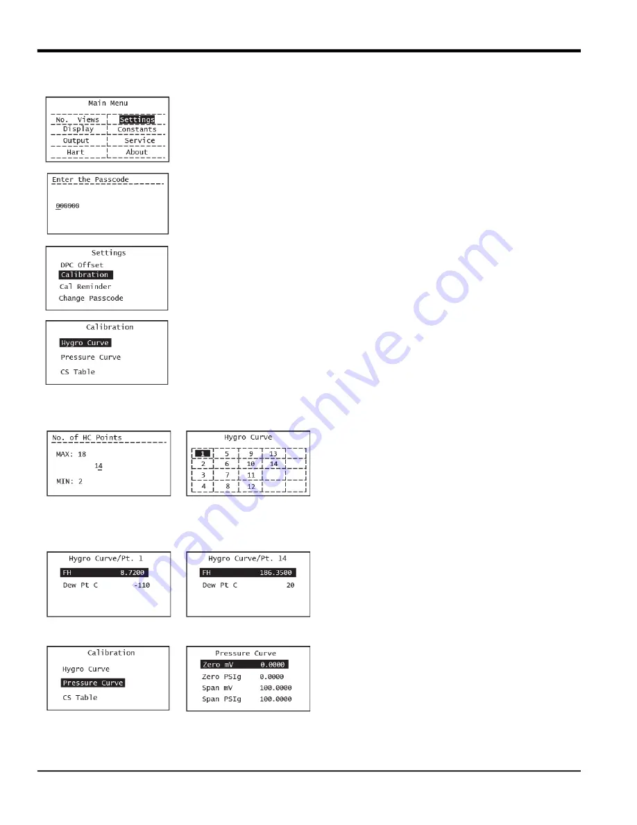
Enter your User password and press Enter. Use the arrow keys to scroll 

to Calibration.  Press Enter.  Select Hygro Curve and press Enter.
This will bring you to the No. of HC points screen. Default number of 

calibration points is 14 (standard HygroRTE calibration), maximum 

number is 18 (extended calibration).  The HC table that appears on 

pressing Enter will display as many points from point 1 as you select.

Select point 1 (or any point you wish to edit) and press Enter.  It is 

advisable to start at the top and check every single calibration point in 

order to ensure the probe calibration curve has been entered 

properly.


The next screen shows the FH (independent 

variable) and Dew Point (dependent variable) 

values for that calibration point. 

As shown on the left, the first calibration point 

typically has a DP setting of -110°C while the last 
(14

th

) point has a DP setting of +20°C.  Use the arrow 

keys to choose either value, enter a desired value 

and press Enter.


Repeat the previous two steps until all of your Hygro 

Curve data points (14 typical, 18 extended) have 

been entered.

To save the data you have to press Enter. If any 

numerical value has changed an intermediate 

screen showing “Save Successful” appears.


If nothing has been changed you will go back to the 

Hygro Curve table screen. 

If you have an optional pressure sensor, you can 

also adjust the 2-point pressure calibration curve by 

choosing the Pressure Curve option and pressing 

Enter.

Summary of Contents for HydroProII

Page 1: ...panametrics com 910 331 A November 2022 HygroProII Moisture Transmitter User s Manual...

Page 2: ......

Page 3: ...ontains one or more registered trademarks of Baker Hughes Company and its subsidiaries in one or more countries All third party product and company names are trademarks of their respective holders Hyg...

Page 4: ...ii no content intended for this page...

Page 5: ...Programming 17 2 1 1 Keypad 19 2 2 Basic Setup 19 2 2 1 Calibration Reminder settings on initial power up 19 2 2 2 Selecting Measurement Parameters 20 2 2 3 Setting up the Display 22 2 2 4 Setting up...

Page 6: ...nterface 42 A 4 1 1 Sensor Input Channels 42 A 4 2 Host interface 42 A 4 2 1 Analog Output 42 A 4 2 2 Digital Output 42 A 4 3 Local Interfaces Jumpers and Switches 42 A 4 3 1 Local Controls and Displa...

Page 7: ...le Point 61 A 9 22 Command 161 0xA1 Read Saturation Table Point 62 A 9 23 Command 162 0xA2 Set Temperature Coefficients 62 A 9 24 Command 163 0xA3 Read Temperature Coefficients 63 A 9 25 Command 166 0...

Page 8: ...2 To enter the password 80 B 2 2 3 Incorrect Passwords 81 B 2 2 4 Exiting without inputting a passcode 81 B 3 Using the Bootloader 81 B 3 1 The Main Menu 81 B 3 1 1 Accessing the sub menus 81 B 3 1 2...

Page 9: ...e information that provides a deeper understanding of the situation but is not essential to the proper completion of the instructions IMPORTANT These paragraphs provide information that emphasizes ins...

Page 10: ...cable to the auxiliary equipment Examples include safety glasses protective headgear safety shoes etc Unauthorized Operation Make sure that unauthorized personnel cannot gain access to the operation o...

Page 11: ...nces that could impact health and the environment In order to avoid the dissemination of those substances in our environment and to diminish the pressure on the natural resources we encourage you to u...

Page 12: ...Preface x HygroProII User s Manual no content intended for this page...

Page 13: ...sensors and read out electronics The HygroProII transmitter uses a state of the art Aluminum Oxide trace moisture sensor that is temperature compensated for optimal accuracy It includes a sample temp...

Page 14: ...application engineer and observe the following guidelines The sample system should be very simple and should contain as few components as possible All or most of those components should be located do...

Page 15: ...he threads Note A 3 4 16 to G 1 2 thread adapter is available from Panametrics 3 Using a 1 1 8 wrench on the probe hex nut tighten the probe securely into the process or sample system fitting CAUTION...

Page 16: ...s can be done in three easy steps as described below Step 1 Connect the shielded 4 wire cable supplied with the HygroProII to the keyed bulkhead connector on the back of the transmitter using the thre...

Page 17: ...surement signal lines and its power supply lines Follow the installation instructions in this section only for units not requiring hazardous classified area protection IMPORTANT To install the HygroPr...

Page 18: ...running TeraTerm or other terminal emulator that can used for field upgrade of the HygroPro firmware proceed to page 9 IMPORTANT To install the HygroProII in a hazardous classified area see Hazardous...

Page 19: ...4 1 2 Standard connection with a HART master handheld device or control system 1 Push the keyed female M8 connector end of the factory supplied cable into the mating male connector on the back of the...

Page 20: ...n the cable over the connectors and turning it clockwise until it is tight 3 Using the flying leads at the other end of the factory supplied cable connect the transmitter to the RS 485 to USB adapter...

Page 21: ...er s manual Note It is the installer s responsibility to follow all applicable technical regulations standards and procedures Figure 10 HygroProII Installation Control Drawing for Division 1 and Divis...

Page 22: ...drawing required Non incendive Field Wiring and Zener Barriers For use in Class I II III Division 2 hazardous areas only Figure 11 Figure 11 HygroProII Installation Control Drawing for Non incendive...

Page 23: ...diagram This installation uses an MTL706 Zener barrier in accordance with the second option listed above Table 3 European Union EU Standards Title Number Date Electrical apparatus for explosive gas a...

Page 24: ...communications with a PC an isolated RS232 RS485 converter mounted in the safe area between the computer and HygroProII must be used The converter is typically powered by its own standard 24 VDC powe...

Page 25: ...eld communication to take place between one or more HART masters and intelligent field transmitters such as the HygroProII Superimposing digital signals on the analog output makes it possible for addi...

Page 26: ...me pair of wires and communicate with the HART master The HART devices are typically set to addresses other than 0 and the loop current mode is set to disabled In multi drop mode the devices will comm...

Page 27: ...o that particular device by HART communication It is written as plain text but is converted into a coded tokenised form for use for greater efficiency The DD file contains the standard table view and...

Page 28: ...t can use for an operator to find each variable or method The standard DD has three top level menus Process Variables Diagram Service and Detailed Setup Each of these menus have several sub menus prov...

Page 29: ...unit will meet its specified Dew Point accuracy within 3 minutes As noted in the previous Chapter dry down response of the HygroRTE probe depends on the initial moisture level of the AlOx sensor If t...

Page 30: ...Loop Signaling Enable Live mA Disable Fixed mA User Passcode Cal Reminder Set Reminder Set Date CS Table Hygro Curve Pressure Curve Point 6 Zero mV Zero Psig Point 16 Point 2 Point 1 Point 15 Constant...

Page 31: ...ng six top level parameters can be accessed and set on the HMI without any passcode a No of Views b Display c Output d HART e Constants f About The Settings menu requires a 6 digit User passcode defau...

Page 32: ...nce the HygroProII does not use a real time clock battery the clock needs to be set upon power up If the user chooses either 6 months or 1 year they are then required to entire the current time and da...

Page 33: ...o choose Press Enter Again any change in this selection is confirmed by a Save Successful prompt flashing on the screen after pressing Enter Use the arrow keys to highlight Temp and press Enter to set...

Page 34: ...ase note each measurement in HygroProII has a pre determined range and resolution and the number of digits after the decimal point is fixed 2 2 3 Setting up the Display To set up the display complete...

Page 35: ...n will disappear from the display After pressing Escape to access the Main Menu use the right arrow key to scroll to Output and press Enter Select the Measurement option and press Enter Use the arrow...

Page 36: ...and press Enter The screen shown on the left appears Enter the Zero and Span values for the range using the same procedure as above In the Output menu select Trim and press Enter The following screen...

Page 37: ...bar could be selected if the desired measurement output is the Equivalent DP 70 bar CAUTION Please be careful to select sample pressure and temperature settings to the best option for the chosen hygro...

Page 38: ...nd press Enter It is advisable to start at the top and check every single calibration point in order to ensure the probe calibration curve has been entered properly The next screen shows the FH indepe...

Page 39: ...under the Service menu see Chapter 3 The end user can adjust all other device parameters shown in the Menu Map in Figure 16 Since the probe calibration data are protected by the User passcode we stron...

Page 40: ...w keys to select Enable Disable HART and press Enter The next screen shown on the left enables you to either disable default is enabled or enable HART on the 4 20 mA output Press Enter In a multi drop...

Page 41: ...tions choose the About option on the Main Menu and press Enter to access the About Menu screen Use the Up and Down arrow keys to select About Display and press Enter The next screen shown on the left...

Page 42: ...Chapter 2 Operation 30 HygroProII User s Manual no content intended for this page...

Page 43: ...ntermediate screen Select the desired Service menu option and press Enter Then follow the on screen instructions After unlocking the display if required and pressing Escape use the arrow keys to scrol...

Page 44: ...AlOx sensor on the probe After completing the above step respond to the Are you sure question Be sure to respond Yes if you wish to save the new information Please note your input has not been accepte...

Page 45: ...accomplish this either return the RTE to Panametrics for recalibration or install a new RTE The HygroProII electronics will automatically read and store the calibration data whenever a new or recalib...

Page 46: ...g the Probe from the Transmitter The HygroII RTE probe is easy to remove from the dismounted transmitter by loosening the two shoulder screws and disconnecting the internal M8 connector cable as shown...

Page 47: ...or cleaned probe back in the transmitter see Figure 19 below This procedure requires completing the following steps 1 Ensure the two shoulder screws at the bottom of the display head are fully loosene...

Page 48: ...mitter 2 Compare the two ambient air readings If the new ambient air reading is within 2 C 3 6 F of the first reading the cleaned probe is properly calibrated and normal operation may be resumed 3 If...

Page 49: ...ime Wet up time 80 C DP 0 5 PPMv to 15 C DP 1500 PPMv in under 4 minutes Dry down time Dry down response is a function of how wet the probe has become and for how long Regardless of its starting and f...

Page 50: ...librated against known moisture concentrations traceable to NIST Calibration Interval Sensor recalibration at Panametrics is recommended every six to twelve months depending on the application Flow Ra...

Page 51: ...000 psig 35 to 345 bar Note PSIG ranges are based on a constant pressure with the value provided at the time of order placement Accuracy 1 of full scale FS Warm up Time Meets specified accuracy within...

Page 52: ...Chapter 4 Specifications 40 HygroProII User s Manual no content intended for this page...

Page 53: ...ication is designed to be a technical reference for HART capable host application developers system integrators and knowledgeable end users It also provides functional specifications e g commands enum...

Page 54: ...A 4 1 Process Interface A 4 1 1 Sensor Input Channels A single removable transducer element moisture probe is connected to the device Refer to the manuals for connection instructions A 4 2 Host inter...

Page 55: ...ees C 0 0 Moisture Dew Point Degrees F 1 0 Moisture Parts Per Million Volume PPMv 2 0 Moisture Parts Per Million Volume PPBv 3 0 Moisture Parts Per Million Volume Natural Gas PPMvNG 4 0 Moisture mg m3...

Page 56: ...mmand 48 Command 48 returns 25 bytes of data with the following status information HART Additional Device Status Byte Bit Error Description Class Device Status Bits Set 0 0 Reserved Warning 4 7 1 No P...

Page 57: ...0 Byte 10 is the Analog Channel Saturated Byte if the Loop Current is saturated the lowest bit will read 1 otherwise all bits are 0 Byte 13 is the Analog Channel Fixed Byte if the loop current is fixe...

Page 58: ...he Command 0 response 12 Read Message Reads the Message contained within the meter 13 Read Tag Descriptor Date Reads the Tag Descriptor and Date contained within the meter 14 Read Primary Variable Tra...

Page 59: ...mmand 148 0x94 Set Temperature Constant Command 149 0x95 Read Temperature Constant Command 150 0x96 Set Dew Point Offset Command 151 0x97 Read Dew Point Offset Command 152 0x98 Set Hygro Curve Number...

Page 60: ...ro value is 4 1 mA then the correction entered should be 0 1 mA to achieve a result of 4 mA Request Data Bytes Response Data Bytes Command Specific Response Codes Byte Format Description 0 Unsigned 8...

Page 61: ...nalog output or fixed 20 mA for trim purposes 1 4 Float mA correction value Byte Format Description 0 Unsigned 8 Enumeration 0 Fixed 20 mA trim 1 Live mA Set for live analog output or fixed 20 mA for...

Page 62: ...utput or fixed mA value 1 4 Float Loop Current Percentage units of percent Byte Format Description 0 Unsigned 8 Enumeration 0 Fixed percent test 1 Live mA Sets live analog output or fixed mA value 1 4...

Page 63: ...and Lower Range Values Unit Code 2 5 Float Upper Range Value 6 9 Float Lower Range Value Code Class Description 0 Success No Command Specific Errors 1 Undefined 2 Error Invalid Selection 3 4 Undefined...

Page 64: ...n the Special span value and special zero value will determine the endpoint mA values instead of 4 mA and 20 mA Request Data Bytes Response Data Bytes 32 Error Busy 33 127 Undefined Byte Format Descri...

Page 65: ...mand Specific Errors 1 Undefined 2 Error Invalid Selection 3 4 Undefined 5 Error Too Few Data Bytes Received 6 Error Device Specific Command Error 7 Error In Write Protect Mode 8 15 Undefined 16 Error...

Page 66: ...to be used in place of a live measurement First byte is an enumeration 0 temperature constant active 1 live measurement instead of constant Request Data Bytes Response Data Bytes 16 Error Access Rest...

Page 67: ...x96 Set Dew Point Offset This command will set the Dew Point Offset adjustment Request Data Bytes Code Class Description 0 Success No Command Specific Errors 1 4 Undefined 5 Error Too Few Data Bytes R...

Page 68: ...of points for the Hygro Curve Request Data Bytes Byte Format Description 0 3 Float Dew Point offset adjustment Code Class Description 0 Success No Command Specific Errors 1 4 Undefined 5 Error Too Few...

Page 69: ...Point Request Data Bytes Byte Format Description 0 Unsigned 8 Number of Hygro Calibration Points Code Class Description 0 Success No Command Specific Errors 1 Error Number of points out of range 2 4...

Page 70: ...of point Code Class Description 0 Success No Command Specific Errors 1 Error Index Out of Bounds 2 127 Undefined Byte Format Description 0 Unsigned 8 Index of Hygro curve point 1 2 Signed 16 Dew Poin...

Page 71: ...tes Byte Format Description 0 3 Float Low End mV 4 7 Float Low End PSIg 8 11 Float High End mV 12 15 Float High End PSIg Byte Format Description 0 3 Float Low End mV 4 7 Float Low End PSIg 8 11 Float...

Page 72: ...uration table points Request Data Bytes 8 11 Float High End mV 12 15 Float High End PSIg Code Class Description 0 Success No Command Specific Errors 1 127 Undefined Byte Format Description 0 Unsigned...

Page 73: ...iption 0 Success No Command Specific Errors 1 127 Undefined Byte Format Description 0 Unsigned 8 Index of saturation table point 1 4 Float Temperature degC 5 8 Float Saturation Constant Byte Format De...

Page 74: ...ecific Response Codes Byte Format Description 0 Unsigned 8 Index of Saturation point Byte Format Description 0 Unsigned 8 Index of Saturation Table point 1 4 Float Tempearture deg C 5 8 Float Saturati...

Page 75: ...lement Request Data Bytes Response Data Bytes 5 Error Too Few Data Bytes Received 6 Error Device Specific Command Error 7 Error In Write Protect Mode 8 15 Undefined 16 Error Access Restricted 8 127 Un...

Page 76: ...ent Set the Hygro Calibration Curve index for the reading of an array element Request Data Bytes Response Data Bytes Command Specific Response Codes Code Class Description 0 Success No Command Specifi...

Page 77: ...d Span Values When the loop measurement type is set to Special then the Special span value and special zero value will determine the endpoint mA values instead of 4 mA and 20 mA Request Data Bytes Res...

Page 78: ...the zero value is 20 1 mA then the correction entered should be 0 1 mA to achieve a result of 20 mA Request Data Bytes 6 Error Device Specific Command Error 7 Error In Write Protect Mode 8 15 Undefine...

Page 79: ...Live mA Read for live analog output or fixed 4 mA for trim purposes 1 4 Float mA correction Value Code Class Description 0 Success No Command Specific Errors 1 4 Undefined 5 Error Too Few Data Bytes...

Page 80: ...9 Error Incorrect Loop Current Mode or Value 10 Undefined 11 Error Loop Current Not Active 12 15 Undefined 16 Error Access Restricted 17 31 Undefined 32 Error Busy 33 127 Undefined Command Function P...

Page 81: ...perature Constant 150 Set Dew Point Offset 151 Read Dew Point Offset 152 Set Hygro Curve Number of Points 153 Read Hygro Curve Number of Points 154 Set Hygro Curve Point 155 Read Hygro Curve Point 156...

Page 82: ...anced user can change the General user password and Advanced user password Request Data Bytes Response Data Bytes Byte Format Description 0 Unsigned 8 Enum User level 0 None 2 Operator User 3 Admin Us...

Page 83: ...meters will not be available after the HygroProII reboots automatically until the password is right and this command is sent to the HygroProII in 10 minutes After the HygroProII reboots automatically...

Page 84: ...nt 148 Set Temperature Constant 149 Read Temperature Constant 150 Set Dew Point Offset 151 Read Dew Point Offset 152 Set Hygro Curve Number of Points 153 Read Hygro Curve Number of Points 154 Set Hygr...

Page 85: ...es Command Specific Response Codes Byte Format Description None Byte Format Description None Code Class Description 0 Success No Command Specific Errors 1 5 Undefined 6 Error Device Specific Command E...

Page 86: ...Types 240 Moisture 240 Dew Point Degrees C 241 Dew Point Degrees F 243 Parts Per Million Volume PPMv 244 Parts Per Million Volume PPBv 245 Parts Per Million Volume Natural Gas PPMvNG 248 mg m3 249 g m...

Page 87: ...7 Long Messages The largest data field used is in the response to Command 183 21 bytes including the two status bytes A 11 8 Non Volatile Memory EEPROM is used to hold the device s configuration para...

Page 88: ...mon practice commands 6 Number of device specific commands 58 Bits of additional device status 11 Alternative operating modes No Burst mode No Write protection Yes Parameter Default value Lower Range...

Page 89: ...M8 connector usually White b Connect the RS485 Data B to the wire corresponding to Pin 4 of the M8 connector Usually Black Figure 21 Pin Out for 6 Pin Female M8 Connector 2 Connect the 5 Wire cable t...

Page 90: ...lect Serial b Select the USB to RS485 adapter from the drop down menu It will be labeled USB Serial Port Figure 22 Select Serial Connection 4 Set the correct settings for the serial terminal a From th...

Page 91: ...correct font and text size Optional for readability a From the menu at the top of the window select Setup Font b Set the font to Arial c Set the font style to Regular d Set the size to 12 e NOTE These...

Page 92: ...or the HygroProII Bootloader is generated using the unique Device ID Number The Bootloader password is separate from the Service passcode This Device ID number is independent from the device Serial Nu...

Page 93: ...un B 3 Using the Bootloader B 3 1 The Main Menu The Main Menu is where you can access all the features of the bootloader Figure 26 Main Menu B 3 1 1 Accessing the sub menus 1 To access the sub menu ty...

Page 94: ...Details Menu will show the version numbers for both the installed bootloader and the installed instrument program If the bootloader cannot verify that the firmware is genuine or if the firmware is cor...

Page 95: ...ils Menu and return to the Main Menu B 3 3 Download and Install New Firmware Menu This is where you can download and install both new bootloader and instrument program firmware The device will require...

Page 96: ...stall new bootloader firmware b Press 2 to install new Instrument program firmware 4 The menu below will be shown a NOTE IMPORTANT It is important that the device does not lose power from this point u...

Page 97: ...YMODEM Send a NOTE If you wish to exit this menu you must press a twice in a row This is a special command required to interrupt the file transfer Figure 31 Firmware Download Menu 6 A file browser win...

Page 98: ...will be shown the file details Figure 33 Downloaded Firmware Details 12 The bootloader will attempt to verify the downloaded firmware binary a If the instrument program firmware is valid it will be i...

Page 99: ...ation data stored in the flash memory of the device For the HygroProII Probe this includes all calibrations calibration date and serial numbers For the HygroProII Display this includes all 4 20mA outp...

Page 100: ...Appendix B HygroProII Field Service Update User Manual 88 HygroProII User s Manual no content intended for this page...

Page 101: ...particular purpose and warranties arising from course of dealing or usage or trade Return Policy If a Panametrics instrument malfunctions within the warranty period the following procedure must be com...

Page 102: ...Warranty 90 HygroProII User s Manual no content intended for this page...

Page 103: ......

Page 104: ...duct and company names are trademarks of their respective holders 910 331 A Customer Support Centers U S A The Boston Center 1100 Technology Park Drive Billerica MA 01821 U S A Tel 800 833 9438 toll f...

Reviews: