Panamax MAX 5300 Owner'S Manual Download Page 9

7

FEATURE DETAILS

USA & Canada (800) 472-5555  •  (415) 499-3900  •  Fax (415) 472-5540

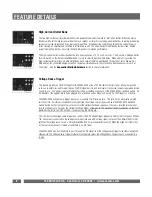
Filtered Outlet Banks 1 & 2:

Eight Outlets (two banks / four outlets per bank) are fed through separate "Balanced, Double L" noise filtration circuits. These
circuits are designed to eliminate AC contamination that is detrimental to the performance of audio or video components like
stereo receivers, VCRs or televisions. The two dedicated filters are carefully engineered to provide power filtration and inter-
component "noise isolation" for both "common mode" (line/neutral-to-ground) and "normal-mode" (line-to-neutral)
EMI/RFI. This means that high-frequency interference will be drastically reduced not only from the incoming power but also
from equipment plugged into the other outlet bank, regardless of what "mode" it occurs in. Even equipment with unground-
ed, 2-blade plugs, receives clean power.

Outlet Bank 1

remains ON continually to provide a constant power source for programmable audio/video components. A

personal video recorder (such as TiVo™) and VCR are two examples of components that require a constant supply of power.
A TiVo™ video recorder relies on continual power to monitor the cable signal and retain its programmed information. A VCR
should be connected to one of these always-on, filtered outlets to maintain correct clock time and programmed recording
information.

Outlet Bank 2

contains four switched outlets that will turn your connected equipment ON or OFF with one of two MAX

®

5300 triggers (Switched Outlets push-button or Voltage Sense Trigger). A 3-position slide switch (Outlet Bank 2 Turn-Off
Switch) located on the rear panel controls the timing for Outlet Bank 2. Together, these outlets can be set as Always-On or
with a turn-off delay of either 10 or 30 seconds to prevent speaker "thump". This switch provides the option of having a total
of eight always-on outlets (Outlet Banks 1 & 2). See the Sequential Startup/Shutdown section for more information.

When set to one of the delay positions (10 or 30 seconds), Outlet Bank 2 outlets will remain as Switched outlets, controlled
by the Switched Outlets push-button and/or the DC Voltage Sense Trigger. In this situation, Outlet Bank 2 outlets will not
power down until after the selected time has elapsed.

1

2

11

Summary of Contents for MAX 5300

Page 1: ...MAX 5300 Owner s Manual 150 Mitchell Blvd San Rafael CA 94903 www panamax com...

Page 2: ...ticated noise filtration circuitry and the world s finest surge protection has resulted in an Audio Video power center that meets the power quality needs for each piece of equipment in your entertainm...

Page 3: ...Telephone Line Protection 9 AC Surge Protection 10 SurgeGate Plus Protection 10 Technical Specifications 11 Contacting Panamax 11 Frequently Asked Questions 12 TABLE OF CONTENTS USA Canada 800 472 55...

Page 4: ...hese components can rapidly draw large amounts of current to replenish their power supply capacitors after thunderous bass notes Line conditioners that utilize coils inductors in series with the AC po...

Page 5: ...USA Canada 800 472 5555 415 499 3900 Fax 415 472 5540 3 CONNECTION DIAGRAM Multi level noise filter and power controller...

Page 6: ...On delay for the two High Current Outlets Choose between 0 10 and 30 seconds Outlet Bank 2 Turn Off Switch 3 position slide switch Allows adjustment of the Turn Off delay for Outlet Bank 2 Choose betw...

Page 7: ...unsafe voltage condition Readings above 150VAC will not be accurate due to the meter s damping characteristics Convenience Outlet A single outlet on the front panel of the MAX 5300 provides an easy to...

Page 8: ...ere is no ground present Line Fault Red LED When this light is ON it is indicating that the wall outlet has a reversed line and neutral wire or there is no ground present This light will remain OFF if...

Page 9: ...e two examples of components that require a constant supply of power A TiVo video recorder relies on continual power to monitor the cable signal and retain its programmed information A VCR should be c...

Page 10: ...and receivers have a 12VDC trigger built in and will transmit a constant power signal when turned on and in use This power signal will initiate the startup or shutdown sequence of the MAX 5300 s switc...

Page 11: ...rcuitry is 700 millivolts 0 7 volts That s less than 1 volt above normal operating levels The circuitry is shielded to prevent interference and has been opti mized to have less than 1dB of signal loss...

Page 12: ...threshold 90VAC the MAX 5300 will perform the following tasks until line voltage returns to a safe level 1 Disconnects power to all connected equipment 2 Unsafe Voltage LED is activated and will blin...

Page 13: ...t Banks 55 dB 100 KHz 1 MHz High Current Outlets 50 dB 100 KHz 1 MHz SURGE PROTECTION UL 1449 Surge Suppression Rating 330V Protection Modes L N L G N G Initial Clamping Level 200V Peak 141V Rms Respo...

Page 14: ...ty documentation for more information What is the difference between a Surge and Spike A spike is a high energy pulse of electricity that lasts for short periods of time a few millisec onds 0 001 seco...

Page 15: ......

Page 16: ......

Reviews: