INSTALLATION
B LT
Blue
®
B LT
Blue
®
B LT
Blue
®
B LT
Blue
®
B LT
Blue
®
B LT
Blue
®
5.
If the
NETWORK / DEMAND
RESPONSE
light is
RED
, the MD2-ZB
is not connected to a ZigBee network.
Proceed to step 6, SETUP
6.
Verify that a BlueBOLT ZigBee, ZigBee-
Ethernet Bridge device is powered on and
within 100 ft. of an active ZigBee device.
1.
Turn
OFF
the equipment that you are
plugging into the MD2-ZB
2.
Plug MD2-ZB into the wall outlet. The
red “
WIRING FAULT
” light indicates an im-
properly wired outlet that must be checked
by a qualified electrician.
4.
Press the
OUTLET 1
and/or
OUTLET 2
buttons to switch power on the respective
outlets.
8.
On MD2-ZB, press the
OUTLET 1
and
OUTLET
2
buttons simultaneously.
The
NETWORK/DEMAND RESPONSE
light will turn
GREEN
once it has joined
the network.
7.
Through the BlueBOLT interface,
enable NETWORK JOINING. Refer to the
user manual for BB-ZIGBEE for detailed
instructions.
3.
Plug your equipment into the AC outlets.
SETUP
NETWORK CONNECT
OUTLET 1
WIRING FAULT
NETWORK DEMAND RESP.
OUTLET 2
OUTLET 1
OUTLET 2
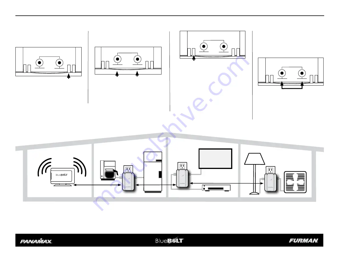
Multible MD2-ZB units can be installed within 100 ft. from an active ZigBee device (BB-ZIGBEE BRIDGE or MD2-ZB).
BB-ZIGBEE
MD2-ZB
MD2-ZB
MD2-ZB
NETWORK CONNECT
OUTLET 1
WIRING FAULT
NETWORK DEMAND RESP.
OUTLET 2
OUTLET 1
OUTLET 2
NETWORK CONNECT
OUTLET 1
WIRING FAULT
NETWORK DEMAND RESP.
OUTLET 2
OUTLET 1
OUTLET 2
NETWORK CONNECT
OUTLET 1
WIRING FAULT
NETWORK DEMAND RESP.
OUTLET 2
OUTLET 1
OUTLET 2
100 ft. Maximum
100 ft. Max.
100 ft. Maximum


