
SPEED-DSL 9.2
SPEED-DSL 9.2/22.10.2004
page 3
1 INSTALLATION
1.1 Unpack and Inspect the Equipment
The following components should be included:
1 SPEED-DSL 9.2
1 power supply
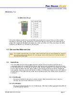
1.2 Power Up the SPEED-DSL 9.2
Plug the power supply into the power adapter port on the back of the SPEED-DSL 9.2 and connect it to
your power source. Verify that the Power LED on the front of the SPEED-DSL 9.2 is illuminated.
N
OTE
Upon start up, the Ethernet link will remain disabled (as indicated by solid illumination of the
Ethernet 100, Act, and Lnk LEDs) until at least one of the four G.SHDSL connections has been
established.
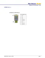
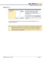
1.3 Configure Bandwidth and Distance
Configuration switches for the G.SHDSL ports are on the back of the SPEED-DSL 9.2, numbered from left
to right, #1-8. Switches #1-3 on the SPEED-DSL 2.3-P work in tandem with one another to provide eight
bandwidth options for the four G.SHDSL ports as a group; bandwidth cannot be configured individually for
the G.SHDSL ports.
N
OTE
Configuration switches #1-3 are used for G.SHDSL bandwidth configuration on the SPEED-DSL 9.2-P
ONLY. The SPEED-DSL 9.2etermines bandwidth via communication with its partner G.SHDSL
provider equipment. Switches #4-8 are not currently used on the SPEED-DSL 9.2 provider or
subscriber models.
Position switches #1-3 on the SPEED-DSL 9.2-P according to the cable distance for your connection and
your desired G.SHDSL bandwidth. Distance capabilities listed in the following table assume the use of 26
American Wire Gauge (AWG) cable. Connections made with cable of a lesser gauge (e.g., 24 AWG) will
link up at greater distances. Your SPEED-DSL 9.2 may not link up if the cable is in poor condition or if the
cable distance is greater than a particular bandwidth will support; if link IS achieved under such conditions,
traffic quality may be affected (e.g., packets may be dropped).


