2
Table of Contents
Introduction
3
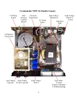
Inside View
4
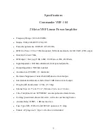
Specifications
5
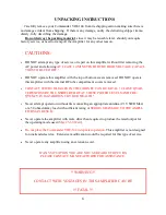
Unpacking Instructions
6
Safety Warnings and Precautions
6
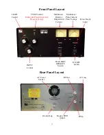
Front & Rear Layout
7
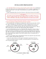
Installation Preparation
8
Operating Procedure
9
Operating Hints
10
Typical Operating Conditions Table
10
Warranty, Service, and Returns
11
HV Power Supply Schematic
12
AC Mains & Step-Start Schematic
13
Control & Metering Board Schematic
14
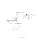
RF Deck Schematic
15
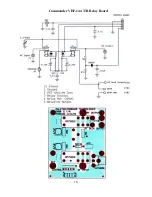
T/R Relay Board Schematic
16
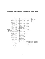
Voltage Doubler Power Supply Schematic 17
PHOTO APPENDIX:
RF Deck
18
Dual Meters
19
Meter Board
20
Step-Start Board
21
Power Supply
22
Summary of Contents for COMMANDER VHF-144
Page 12: ...12 Commander VHF 144 HV Power Supply...
Page 13: ...13 AC Mains and Step Start Board VHF 144 13 5VAC...
Page 14: ...14 Control and Metering Board VHF 144...
Page 15: ...15 RF Deck VHF 144...
Page 16: ...16 Commander VHF 144 T R Relay Board...
Page 17: ...17 Commander VHF 144 Voltage Doubler Power Supply Board...
Page 20: ...20 Meter Board Cathode Fuse...
Page 21: ...21 Step Start Board AC Main Fuse 20A x 2 AC Interlock Step Start Relays x 4...
Page 22: ...22 Power Supply 470uF Capacitor 450 vdc x 8 HV Sense RF Output...
Page 23: ...23...


