
(
Optional
) If you are not able to connect to the web interface, check the status of the firewall by connecting to the
micro USB or RJ-45 console port. The console connection provides access to firewall boot messages, maintenance
mode, and the command line interface (CLI).
For information about downloading the micro USB Windows driver and instructions on how to connect using a Mac or Linux
computer, refer to
https://docs.paloaltonetworks.com/resources/micro-usb-console-port
.
A
B
C
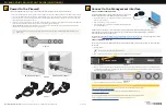
Power On the Firewall
The PA-820 firewall has one power supply. The PA-850 firewall has two power supplies for power redundancy.
1
Remove the nut and star washer from the ground stud shown in Figure 7 and attach a 14-AWG ground cable (not included) to the ground stud.
2
Secure the ground cable to the stud using the star washer and nut and torque to 25 in-lbs. Connect the other end of the cable to earth ground.
3
Connect the AC power cord to the power input on the back of the firewall, as shown in Figure 8. On a PA-850 firewall, secure the cord to the
power supply using the Velcro strap as in Figure 9.
4
Connect the other end of the power cord to an AC power source. After power is connected, the firewall powers on as indicated by the PWR LED
on the front of the firewall. On a PA-850 firewall, the LED on the power supply also shows green.
5
(
PA-850 firewall only
) To provide power redundancy, connect a power cord to the second power supply, secure the cord using the Velcro
strap, and connect the other end of the cord to an AC power source.
Figure 9
PA-820 Power Input
PA-850 Power Inputs
Figure 8
Figure 7
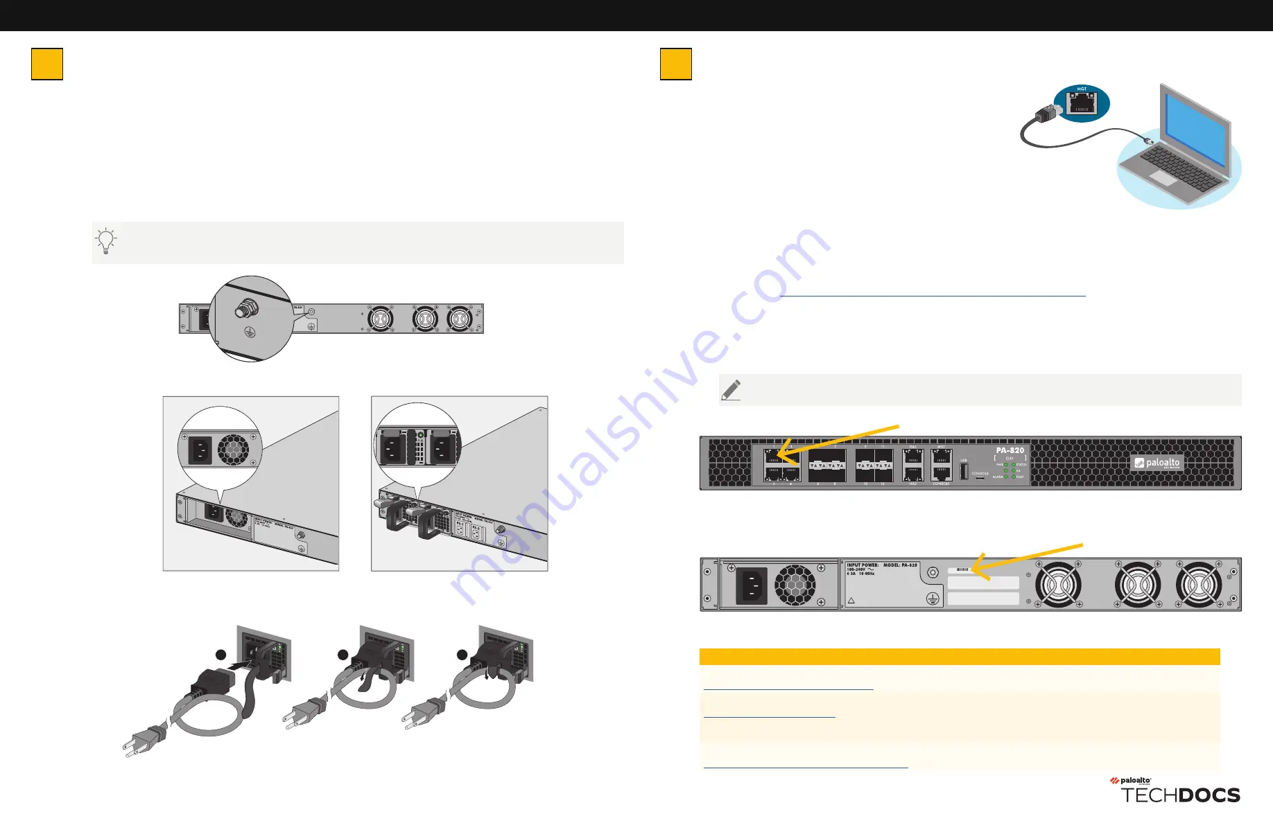
Connect to the Management Interface
Connect with Standard Firewall
Connect the standard RJ-45 Ethernet cable from the RJ-45 port on your
computer to the MGT port on the firewall, as shown in Figure 10.
1
Change the IP address on your computer to an address in the 192.168.1.0/24
network, such as 192.168.1.2.
2
From a web browser, go to https://192.168.1.1.
3
When prompted, log in to the web interface using the default username and
password (admin/admin).
Figure 10
PA-800 SERIES QUICK START GUIDE (CONTINUED)
3
Connect the second power cord through a different circuit breaker to provide power redundancy and allow for electrical circuit
maintenance.
4
Where To Go Next
To learn more about the firewall, refer to the PA-800 Series Next-Gen Firewall Hardware Reference Guide:
https://docs.paloaltonetworks.com/hardware
.
To learn how to configure Palo Alto Networks firewalls, go to the Technical Documentation portal:
https://docs.paloaltonetworks.com
.
(Use the Getting Started information in the PAN-OS Administrator’s Guide for initial configuration tasks.)
Start here to Register and Set Up your firewall and access all resources and support tools:
https://go.paloaltonetworks.com/CustomerLaunchPad
Page 2 of 2
docs.paloaltonetworks.com
| © 2020 | Palo Alto Networks, Inc. | Part Number: 810-000261-00F
Connect with ZTP Firewall
To connect your PA-800 Series firewall using Zero Touch Provisioning (ZTP), you must have the PAN-PA-820-ZTP or PAN-
PA-850-ZTP.
1
Unbox the firewall.
2
Connect the ZTP port (Ethernet port 1) on the firewall to the broadband connection. See Figure 11.
3
Power on the firewall.
4
Follow the instructions provided by your Panorama administrator to register your ZTP firewall. You will have to enter the serial number
(12-digit number identified as S/N) and claim key (8-digit number). These numbers are on stickers attached to the back of the device. See
Figure 12 for the location of the claim key.
5
Contact your Panorama administrator if you require further assistance.
Do not power on the firewall until Step 2 is complete.
FANS
Figure 11
!
15103396
Figure 12


