Service the PA-5200 Series Firewall
STEP 5 |
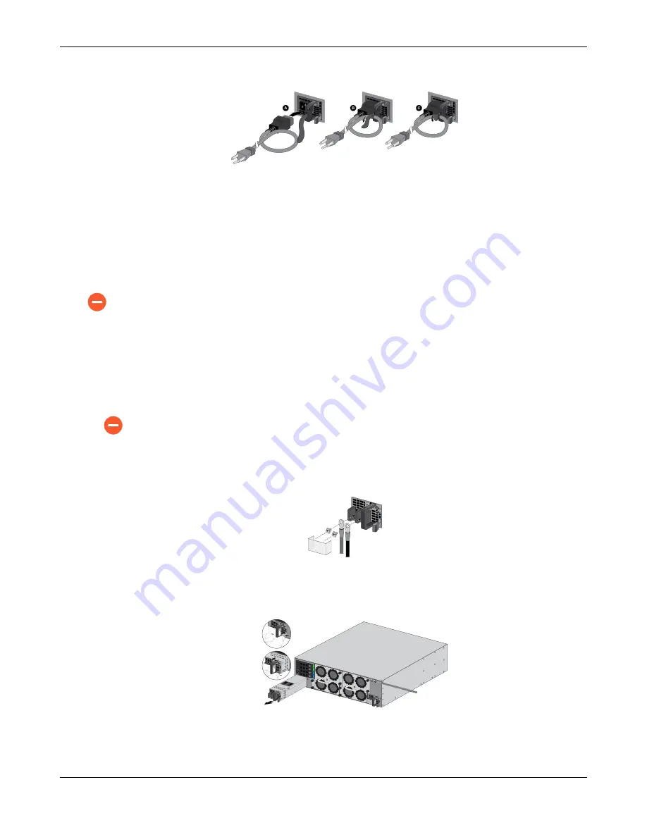
Connect the AC power cord to the power supply input and secure it to the power supply
using the Velcro strap.
STEP 6 |
Connect the other end of the power cord to a grounded AC power source. The new power
supply automacally powers on, the OK LED turns green, the FAIL LED turns off, and the
power LED (PWR 1 or PWR 2) on the front of the firewall turns green.
Replace a DC Power Supply on a PA-5200 Series Firewall
The following procedure describes how to replace a DC power supply.
To avoid injury to yourself or damage to your Palo Alto Networks
®
hardware or the data
that resides on the hardware, read the
.
STEP 1 |
Idenfy the failed power supply by viewing the power supply LED on the back of the firewall;
when there is a failure, the FAIL LED on the failed power supply turns solid yellow. For more
details on the power supply LEDS, see
Interpret the LEDs on a PA-5200 Series Firewall
.
STEP 2 |
Power off the DC power source that is connected to the failed DC power supply.
Ensure that the power is off before connuing to the next step.
STEP 3 |
Remove the plasc cover that protects the DC input terminals and then use a Phillips-head
screwdriver to remove the screws holding the posive and negave DC cables to the DC
input terminals.
STEP 4 |
Grasp the handle on the failed power supply and then simultaneously press the release lever
to the le and pull the power supply outward to remove it.
PA-5200 Series Next-Gen Firewall Hardware Reference
35
©
2021 Palo Alto Networks, Inc.


