PA-3200 SERIES NEXT-GEN FIREWALL QUICK START GUIDE
1
2
Before You Begin
Use this guide to install and begin setting up your Palo Alto Networks
®
PA-3220, PA-3250, or PA-3260 next-generation firewall. Refer
to the PA-3200 Series Next-Gen Firewall Hardware Reference at
https://www.paloaltonetworks.com/documentation/platforms
for
safety information, specifications, and more detailed procedures for installing your firewall.
•
Verify that the installation site has an AC (or DC) power source. By default, the firewall ships with AC power supplies; if you need to
use DC power, contact your sales representative or contact the Palo Alto Networks Sales department
(
https://paloaltonetworks.com/company/contact-support.html
) to order two DC power supplies and then use the installation
procedures in the PA-3200 Series Next-Gen Firewall Hardware Reference to connect power to the firewall.
•
Ensure that you have both a #1 and #2 Phillips-head torque driver available. Use the #1 Phillips-head bit to attach the rack-mount
brackets to the firewall and use the #2 bit to secure the rack-mount brackets to the equipment rack posts.
•
Unpack the equipment and verify that you received the following items:
Rack Mount the Firewall
The PA-3200 Series firewall ships with two rack-mount brackets for an installation in a two-post or four-post 19-inch equipment rack.
If
you install the firewall in a four-post equipment rack and you require additional support, you can purchase a four-post rack kit from Palo
Alto Networks that secures the firewall to the back posts of the rack. Both procedures are covered in this guide.
Install the Firewall in a Two-Post or Four-Post Equipment Rack
1.
Attach one rack-mount bracket to each side of the firewall using four #8-32 x 5/16” screws for each bracket and torque each
screw to 15 in-lbs. For a two-post rack, we recommend that you install the brackets in the mid-mount position as shown in
Figure 1
. For a four-post rack, we recommend that you install the brackets in the front-mount position as shown in
Figure 2
.
Ensure that the equipment rack is properly anchored so it can support the weight of the installed equipment without
tipping.
2.
With help from another person, hold the firewall in the rack and secure the rack-mount brackets to the rack posts using four
screws for each bracket (
Figure 3
). Use the appropriate screws (#10-32 x 3/4” or #12-24 x 1/2”) for your rack and torque each
screw to 25 in-lbs. Use cage nuts (not provided) to secure the screws if the rack has square holes.
Figure 1
Attach Front Rack-Mount Brackets in the
Mid-Mount Position
Figure 3
Secure the Firewall to a Two-Post Rack
Figure 4
Attach Four-Post Side Rails
Figure 5
Install the Firewall in the Four-Post Rack
Qty
Description
1
PA-3200 Series next-generation firewall.
2
AC power cords.
2
Velcro straps to secure the AC power cords to the power supplies.
1
DB-9 female to RJ-45 male console cable.
1
Standard Type-A USB to micro USB console cable.
1
Standard RJ-45 CAT6 Ethernet cable for management (MGT) port access.
2
Rack-mount brackets to secure the firewall to a two-post or four-post equipment rack.
8
#8-32 x 5/16” rack-mount bracket screws to attach the front rack-mount brackets to the firewall.
8
#10-32 x 3/4” rack-mount screws to secure the front rack-mount brackets to a rack with #10-32 threaded holes.
8
#12-24 x 1/2” rack-mount screws to secure the front rack-mount brackets to a rack with #12-24 threaded holes.
1
End User License Agreement (EULA).
1
China Restriction of Hazardous Substances (RoHS) declaration.
paloaltonetworks.com/documentation | © 2018 | Palo Alto Networks, Inc. | Part Number: 810-000287-00B | Page 1
(
Optional
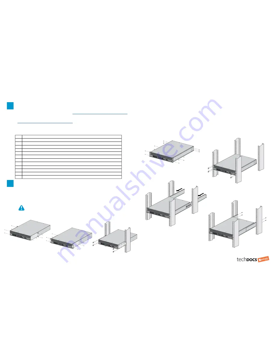
) Install the Firewall in a Four-Post Equipment Rack Using the Four-Post Kit
The four-post rack kit replaces the rack brackets that ship with the firewall to provide additional support to the back of the firewall.
All hardware (screws and brackets) required to install the rack kit is included with the kit.
1.
Remove the front rack-mount brackets (if installed) from each side of the firewall. (
Figure 1
shows the front brackets.
)
2.
Attach one four-post side rack-mount rail to each side of the firewall. Use four #8-32 x 5/16” screws for the front four screw
holes of each side rail and three #6-32 x 5/16” screws for the three back screw holes of each side rail (
Figure 4
) and torque
each screw to 15 in-lbs.
3.
With help from another person, hold the firewall in the rack and secure the side rails to the front rack posts using four screws
for each rail (
Figure 5
). Use the appropriate screws (#10-32 x 3/4” or #12-24 x 1/2”) for your rack and torque each screw to 25
in-lbs. Use cage nuts (not provided) to secure the screws if the rack has square holes.
4. Slide one four-post back rack-mount rail into each of the two previously installed side rack-mount rails (
Figure 6
), and secure
the back rails to the back rack posts using four screws for each bracket (#10-32 x 3/4” or #12-24 x 1/2” screws), and torque
each screw to 25 in-lbs (
Figure 7
).
Figure 6
Slide the Back Rails into the Side Rails
Figure7
Secure the Back Rails to the Back Rack Posts
#8-32 x 5/16”
Screws
#6-32 x 5/16”
Screws
Figure 2
Attach Front Rack-Mount Brackets
in the Front-Mount Position