background image

ION 1200 Overview

ION 1200-C-NA/ROW Front Panel

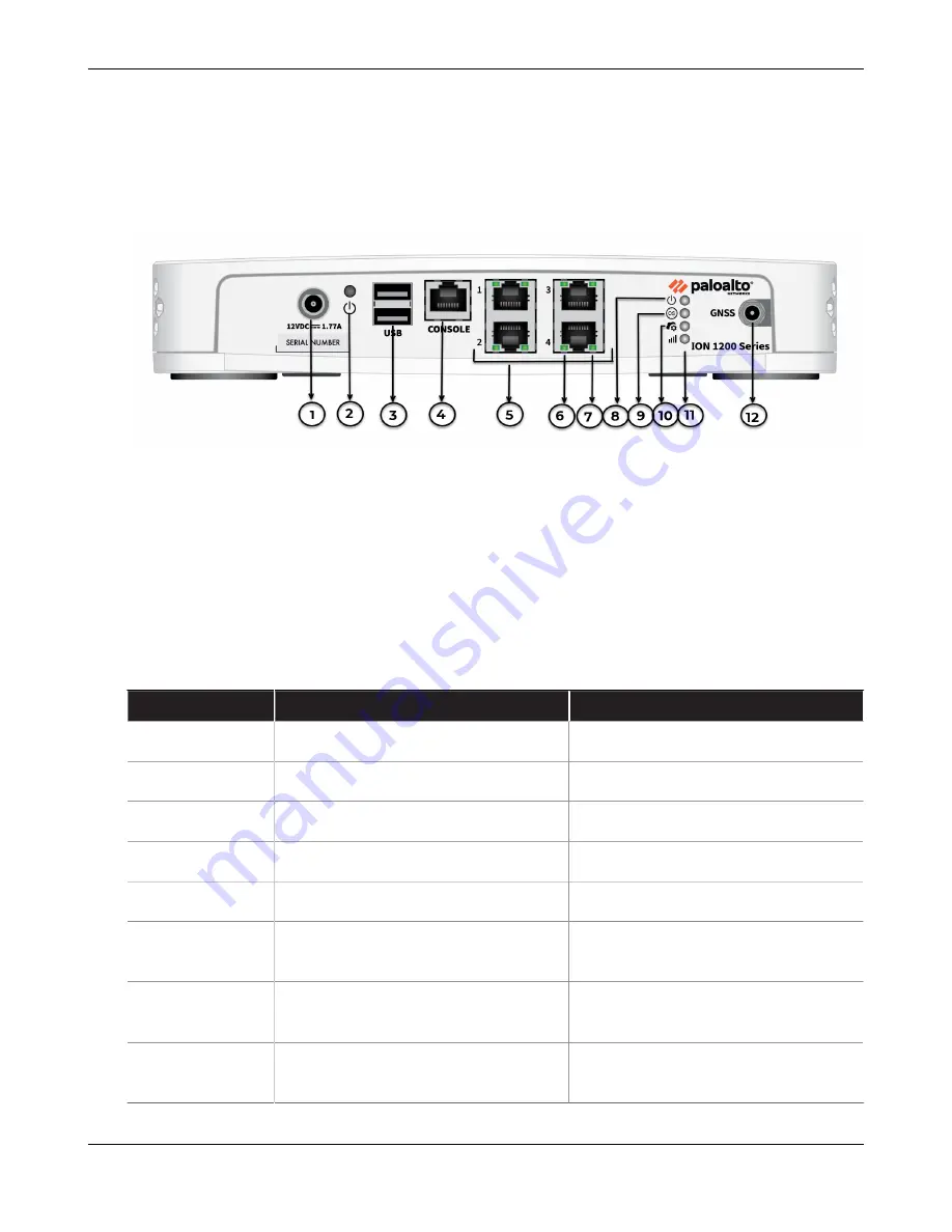
The front panel of the ION 1200-C-NA and ION 1200-C-ROW are idencal. The following image

shows the front panel of the ION 1200-C-NA/ROW and the table describes the front panel

components.

Item

Component

Descripon

1

Power

Power input.

2

Restart Buon

Restart buon.

3

USB Port

USB 3.0 (reserved for future use).

4

Console Port

RJ-45 Serial console port.

5

Ethernet Ports

RJ-45 WAN/LAN ports.

6

Link Speed LED

On ethernet ports 1-4, the le LED

indicates the link speed.

7

Acvity LED

On ethernet ports 1-4, the right LED

indicates the acvity on the port.

8

Power LED

Power LED; the LED turns green

when powered on.

ION 1200 Hardware Reference

20

©

2021 Palo Alto Networks, Inc.

Summary of Contents for ION 1200

Page 1: ...ION 1200 Hardware Reference docs paloaltonetworks com...

Page 2: ...docs paloaltonetworks com search html Have feedback or ques ons for us Leave a comment on any page in the portal or write to us at documenta on paloaltonetworks com Copyright Palo Alto Networks Inc w...

Page 3: ...ck Panel 27 ION 1200 LEDs 29 Installa on Kit Components 31 ION 1200 Compliance Statement 32 Install the ION 1200 35 Install Antennas 36 Insert SIM Cards 39 Install the ION 1200 on a Flat Surface 43 In...

Page 4: ...Table of Contents ION 1200 Hardware Reference 4 2021 Palo Alto Networks Inc...

Page 5: ...Before You Begin Tamper Proof Statement Third Party Component Support Product Safety Warnings 5...

Page 6: ...uct The tracking number provided to you electronically when ordering the product matches the tracking number that is physically labeled on the box or crate The integrity of the tamper proof tape used...

Page 7: ...egin Third Party Component Support Before you consider installing third party hardware read the Palo Alto Networks Third Party Component Support statement ION 1200 Hardware Reference 7 2021 Palo Alto...

Page 8: ...sta que est en contact avec votre peau et que l autre extr mit du bracelet est raccord e la terre Use grounded and shielded Ethernet cables to ensure agency compliance with electromagne c compliance...

Page 9: ...ce with the FCC guidelines for Human Exposure to Radio Frequency Electromagne c Fields FCC Bulle n 65C 01 01 Evalua ng Compliance with the FCC guidelines for Human Exposure to Radio Frequency Electrom...

Page 10: ...with Innova on Science and Economic Development ISED Canada s license exempt RSS s Opera on is subject to the following two condi ons This device may not cause interference This device must accept any...

Page 11: ...mits set forth by each hospital The use of so ware or rmware not supported provided by the manufacturer may result in the equipment being no longer compliant with the regulatory requirements Australia...

Page 12: ...Before You Begin ION 1200 Hardware Reference 12 2021 Palo Alto Networks Inc...

Page 13: ...rview ION 1200 ION 1200 Hardware Speci ca ons ION 1200 Front Panel ION 1200 C NA ROW Front Panel ION 1200 C 5G WW Front Panel ION 1200 Back Panel ION 1200 C NA ROW Back Panel ION 1200 C 5G Back Panel...

Page 14: ...deployment of ATMs or kiosk systems or as a secondary backup link to improve the resilience of the branch WAN The variants of the ION 1200 series are ION 1200 Enterprise small branch ION 1200 C NA an...

Page 15: ...45 4 x RJ 45 USB 2 x Type A 2 x Type A 2 x Type A 2 x Type A eMMC Storage 32GB 32GB 32GB 32GB Throughput 250Mbps 250Mbps 250Mbps 250Mbps Memory 4GB 4GB 4GB 4GB Power 25W 40W 40W 40W Mechanical System...

Page 16: ...all Cellular speci ca ons SIM Slot Size Not Supported Nano 4FF Nano 4FF Nano 4FF Radio Main TX RX1 AUX RX2 GNSS Main TX RX1 AUX RX2 GNSS Main TX1 RX1 MIMO1 TX2 RX2 MIMO2 RX3 GNSS L5 AUX RX4 GNSS L1 An...

Page 17: ...ION 1200 C 5G WW B28 B29 B30 B32 B34 B38 B39 B40 B41 B42 B46 B48 B66 B71 3G B1 B2 B3 B4 B5 B6 B8 B9 B19 Cellular Carrier Cer ca on Not Supported AT T Verizon PTCRB T Mobile GCF AT T PTCRB T Mobile ION...

Page 18: ...B Port USB 3 0 reserved for future use 4 Console Port RJ 45 Serial console port 5 Ethernet Ports RJ 45 WAN LAN ports 6 Link Speed LED On ethernet ports 1 4 the le LED indicates the link speed 7 Ac vit...

Page 19: ...0 Overview Item Component Descrip on 10 Controller LED Controller LED the LED turns green on successful connec on with the Prisma SD WAN controller ION 1200 Hardware Reference 19 2021 Palo Alto Networ...

Page 20: ...rip on 1 Power Power input 2 Restart Bu on Restart bu on 3 USB Port USB 3 0 reserved for future use 4 Console Port RJ 45 Serial console port 5 Ethernet Ports RJ 45 WAN LAN ports 6 Link Speed LED On et...

Page 21: ...on successful connec on with the Prisma SD WAN controller 11 Cellular LED Cellular LED the LED indicates signal strength Refer ION 1200 LEDs to know more 12 Antenna Connector Antenna SMA F Connectors...

Page 22: ...1 4 the le LED indicates the link speed 7 Ac vity LED On ethernet ports 1 4 the right LED indicates the ac vity on the port 8 Power LED Power LED the LED turns green when powered on 9 OS LED Opera ng...

Page 23: ...ION 1200 Overview Item Component Descrip on MIMO1 TX2 RX2 MIMO2 RX3 GNSS L5 AUX RX4 GNSS L1 ION 1200 Hardware Reference 23 2021 Palo Alto Networks Inc...

Page 24: ...1200 and the table describes the back panel components Item Component Descrip on 1 Serial Number Serial number of the ION device 2 Part Number Part number of the ION device 3 QR Code QR code links to...

Page 25: ...device and ION 1200 C ROW and the table describes the back panel components Item Component Descrip on 1 and 10 Antenna Connectors Antenna SMA F connectors 2 Serial Number Serial number of the ION dev...

Page 26: ...IM slots for cellular network connec vity 7 QR Code QR code links to the SIM installa on sec on of the Hardware Reference 8 Screws M3 screws 9 QR Code QR code links to the ION 1200 Hardware Reference...

Page 27: ...tor Antenna SMA F connectors 2 Serial Number Serial number of the ION device 3 Part Number Part Number of the ION device 4 IMEI Label IMEI number of the device 5 SIM Cover SIM cover that covers the SI...

Page 28: ...ION 1200 Overview Item Component Descrip on 9 QR Code QR code links to the ION 1200 Hardware Reference ION 1200 Hardware Reference 28 2021 Palo Alto Networks Inc...

Page 29: ...the device is connected to the controller Red LED indicates the device is a emp ng to connect to the controller Link Ac vity On ethernet ports the right LED displays the link ac vity The LED blinks w...

Page 30: ...on the signal strength 25 blinks in 10 seconds Good signal strength 10 blinks in 10 seconds Fair signal strength 5 blinks in 10 seconds Poor signal strength You can also the view the signal strength o...

Page 31: ...r plywood 7x Drywall anchors and screws 1 25 to mount the device and power adapter bracket to a drywall or similar material that cannot securely accommodate wood screws 1x Power adapter wall mount kit...

Page 32: ...E European Union EU Electromagne c Compa bility Direc ve The ION devices that do not contain radios ION 1200 comply with the requirements set out in the Electromagne c Compa bility Direc ve 2014 30 EU...

Page 33: ...o an outlet on a circuit that is di erent from the one to which the receiver is connected Consult the dealer or an experienced radio TV technician for help ICES Canadian EMC Compliance Statement This...

Page 34: ...ION 1200 Overview ION 1200 Hardware Reference 34 2021 Palo Alto Networks Inc...

Page 35: ...to install the ION 1200 series Install Antennas Insert SIM Cards Install the ION 1200 on a Wall Install the ION 1200 on a Flat Surface Install the ION 1200 in a 19 inch Equipment Rack Install the ION...

Page 36: ...N 1200 C 5G WW devices support mul band antennas which can be easily secured to the device The ION 1200 C NA and ION 1200 C ROW have three antenna SMA F connectors The ION 1200 C 5G WW has four antenn...

Page 37: ...band 2 6dBi in 2170MHz band 1 7dBi in 3300MHz band 3 8dBi in 4400MHz band VSWR 3 1 Feed Impedance 50 Power Handling 30 dBm Interface SMA F Connectors Antenna Dimensions 229 mm x 28 mm x 14 mm L x W x...

Page 38: ...device by viewing the Cellular LED signal strength indicator or on the Prisma SD WAN web interface Do not place the antennas close to or poin ng to one another or layover one another Make sure the pow...

Page 39: ...00 C ROW and ION 1200 C 5G WW devices support two SIM slots to enable mul ple mobile network connec vity STEP 1 Remove the SIM cover by unfastening the two M3 screws using a type one Phillips screwdri...

Page 40: ...n gure below Ensure to correctly insert the SIM in the SIM slot incorrect inser on may damage the SIM By default SIM slot 1 is the primary SIM If you have only one SIM it is recommended to use the slo...

Page 41: ...Install the ION 1200 ION 1200 Hardware Reference 41 2021 Palo Alto Networks Inc...

Page 42: ...er inser ng the SIM place the SIM cover back on the device To eject the SIM from the device gently push the SIM inward using a nger p and release it before pulling it out ION 1200 Hardware Reference 4...

Page 43: ...1200 series ships with rubber feet a ached to each corner of the device As pictured below the ION 1200 device can be horizontally situated on a at surface You can also install the ION 1200 on a rack o...

Page 44: ...ION 1200 Install the ION 1200 on a Wall Install an ION 1200 on a drywall or plywood wall using the wall mount kit as described in the following procedure ION 1200 Hardware Reference 44 2021 Palo Alto...

Page 45: ...re the wall mount screws line up with the device mount holes print the Wall Mount Template in landscape mode and actual size in the Print op ons to ensure the screw hole markers line up correctly Ensu...

Page 46: ...Install the ION 1200 ION 1200 Hardware Reference 46 2021 Palo Alto Networks Inc...

Page 47: ...protrudes 1 4 6cm from the wall Repeat this step for the other three screw loca ons unless either is located over wood in which case use a 75 wood screw instead of a drywall anchor and screw Plywood...

Page 48: ...he notches in the bracket to prevent the power cord from falling out A er you secure the power adapter to the bracket mount the bracket next to the device using wood or drywall screws as appropriate T...

Page 49: ...Install the ION 1200 ION 1200 Hardware Reference 49 2021 Palo Alto Networks Inc...

Page 50: ...ad and print the following wall mount template to secure the template to the wall where you intend to mount the device and use it to mark the loca on for each of the four wall mount screws ION 1200 Ha...

Page 51: ...ON 1200 device in a 19 rack The installa on hardware consists of a metal base and two rails To ease installa on rst install the device in the racktray and then install the assembled racktray into the...

Page 52: ...of the xed moun ng brackets to create a moun ng rail Repeat for the second moun ng rail The adjustable and xed brackets are the same for the le and right side STEP 2 Align the bo om edge of the moun n...

Page 53: ...P 3 Secure the rails to the equipment frame with moun ng screws not provided compa ble with your equipment frame Tighten the screws to their recommended torque value ION 1200 Hardware Reference 53 202...

Page 54: ...200 STEP 4 With the front of the device facing forward align the four rubber feet on the bo om of the device to the slo ed holes in the provided moun ng tray ION 1200 Hardware Reference 54 2021 Palo A...

Page 55: ...Install the ION 1200 STEP 5 Secure the device in place using three of the provided 6 32 x 3 16 Long Flathead screws ION 1200 Hardware Reference 55 2021 Palo Alto Networks Inc...

Page 56: ...N 1200 STEP 6 Slide the device power supply into the marked posi on and fasten the provided velcro strap around the power supply un l it is secure in place ION 1200 Hardware Reference 56 2021 Palo Alt...

Page 57: ...e wraps bind and secure the power supply cable to the metal hooks in the moun ng tray STEP 8 Slide the moun ng tray into the rails previously xed to the equipment rack Stop when the front ange on the...

Page 58: ...holes in the equipment frame Secure the moun ng tray to the equipment frame on both sides using 3 screws each not provided The screws must be compa ble with your equipment frame STEP 10 Proceed to Pow...

Page 59: ...the following ways Shut down using the Device Toolkit commands Run the device toolkit command debug shutdown to shut down the device Ensure the device is physically accessible to turn it back on befor...

Page 60: ...Install the ION 1200 ION 1200 Hardware Reference 60 2021 Palo Alto Networks Inc...

Page 61: ...ubleshoot ION 1200 This sec on lists the most common issues that you may face Troubleshoot the issue by following the resolu on steps men oned in the table Troubleshoot Common Issues with the ION 1200...

Page 62: ...the antenna connec vity 2 Try to move the router to a di erent loca on where there are fewer or no obstacles to the signal for example near a window Keep the device away from large metal objects such...

Page 63: ...e router to a di erent loca on where there is less or no obstacles to the signal for example near a window 4 Check for obstacles to the signal and interference from other devices A ached no IP address...

Page 64: ...Troubleshoot ION 1200 ION 1200 Hardware Reference 64 2021 Palo Alto Networks Inc...

Reviews: