Palmgren 83115 Operating Manual & Parts List Download Page 6

6

Palmgren Operating Manual & Parts List

83115

OPERATION

CAUTION:

Always observe the following safety precautions:

Make sure that blade guides and thrust bearings are positioned
and adjusted correctly to prevent sideways and rearward
movement of the blade. Adjust upper guide to just clear work-
piece.

Check to make sure blade is tensioned and tracking properly.
Do not over tension the blade in order to prevent premature
blade wear and breakage. Avoid under tensioning to eliminate
back and forth, side to side blade movement as it cuts.

Use proper blade and speed for the cutting operation.

After turning saw on, allow blade to come to full speed before
attempting any cutting operation.

Support workpiece properly and use a smooth steady feed to
guide work through the cut. Use push sticks or push blocks
when required.

Keep hands away and out of line with moving parts.

Always wear eye protection.

REMOVING BLADE

Refer to Figures 8, 9 and 10 (pages 12, 14 and 16).

WARNING:

Disconnect band saw from power source when

changing or adjusting blades. Wear leather gloves when handling
band saw blades. Never wear gloves when operating saw.

Loosen three screws (Figure 9, Ref. No. 5). Remove blade guards
(Figure 9, Ref. Nos. 4 and 38). Loosen handle (Figure 8, Ref. No.
30) and rotate handwheel (Figure 8, Ref. No. 23) to release blade
tension. Be careful; blade may spring from saw when tension is
released. Remove table stud (Figure 10, Ref. No. 16), take out the
released blade and replace with another blade.

INSTALLING BLADE

Although many of the adjustments may not be altered when
blade is removed, every adjustment should be checked prior to
using a newly installed blade.

Follow safety precautions every time saw is operated.

Make sure blade teeth are pointing down towards table. Turn
blade inside out if  necessary.

Slip new blade into table slot and over upper and lower blade
wheels and center blade on blade wheels. Slide blade in
between blade guides. Replace table stud. Replace blade
guards after blade guide adjustment.

Tension and track blade as described in the following  sections.

TENSIONING BLADE

Refer to Figure 8, page 12.

Tension blade by rotating handwheel (Ref. No. 23). Be sure
blade guides do not interfere with blade path.

Tighten blade until it is properly  tensioned. 

A properly tensioned blade will ring slightly when back of
blade is plucked (like a string on an instrument).

NOTE:

Check tension of new blade. Additional tension may be

required after a few minutes of operation.

TRACKING BLADE

Refer to Figure 8, page 12.

Track blade after it has been tensioned. A change in blade ten-
sion will affect wheel alignment.

Proper tracking is achieved when drive and idler wheels are
aligned. Knob (Ref. No. 29) is used to tilt tracking bar (Ref. No.
13) and align blade wheels.

Loosen hex nuts (Ref. No. 30) which lock tracking knob (Ref. No.
29). Turn idler wheel (Ref. No. 7) by hand and observe how
blade rides on wheels.

If blade rides away from cabinet, turn knob clockwise to tilt
idler wheel up.

If blade rides into  cabinet, turn tracking knob counterclockwise.

When blade is tracking properly, lock position by holding knob
and tightening hex nuts (Ref. No. 30) against the cabinet.

ALIGNMENT OF DRIVE WHEEL

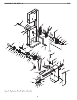
Refer to Figure 11, page 18.

NOTE:

Only attempt adjusting drive wheel alignment if blade 

cannot be properly tracked with tracking adjustment alone.

A blade under high tension may also pull drive wheel out of
alignment.

Adjust alignment of drive wheel using hex head bolts (Ref. No. 9).

BLADE GUIDES

NOTE:

Adjust blade guides only after blade has been properly 

tensioned and tracked.

Blade guides support blade at sides and rear of blade, and 
prevent twisting or deflection.

Blade guides should not touch blade when no workpiece is in
contact with blade. Adjust guides as described in following 
sections.

UPPER BLADE GUIDES

Refer to Figure 9, page 14.

Upper blade guides employ guide pins for side support and a
ball bearing on an adjusting pin at rear.

Upper guide bracket (Ref. No. 13) should be positioned so
guide on either side of blade will support as much of blade
width as possible without interfering with the tooth set.

Adjust bracket depth by loosening bolts (Ref. Nos. 9 and 12)
and sliding brackets into position. Secure position of upper
guide casting by tightening bolts.

Loosen set screws (Ref. No. 15) and adjust guide pins (Ref. No.
14) to side of blade. Use a feeler gauge to check that guide pins
are .002” away from blade.

Lock adjustment by tightening set screws.

Adjust thrust bearing (Ref. No. 17) at rear of blade by loosening
set screw (Ref. No. 15).

Position thrust bearing .002” away from back of blade.

Secure position of thrust bearing by tightening set screw.

Adjust the height of upper guide casting to clear the  workpiece
by 

1

/

4

”. Loosen knob (Ref. No. 30) and rotate height adjustment

knob (Ref. No. 22) until upper blade guide bracket clears work-
piece by 

1

/

4

”. Tighten knob.

LOWER BLADE GUIDES

Refer to Figure 9, page 14.

Lower blade guides employ two guide blocks for side support.
Lower guide bracket is spaced close to table surface to mini-
mize unsupported length of blade.

Loosen screw (Ref. No. 5) and remove blade guard (Ref. No. 38).

Loosen bolt (Ref. No. 19) to position lower guide bracket on
alignment block (Ref. No. 31). Adjust lower guide bracket so
guide blocks do not interfere with blade set. Loosen set screws
(Ref. No. 23) for guide blocks (Ref. Nos. 21 and 34) and adjust
guide blocks to .002” from each side of blade.

Summary of Contents for 83115

Page 1: ...operating manual parts list 83115 15 7 SPEED METAL WOOD CUTTING BAND SAW Read carefully and follow all safety rules and operating instructions before first use of this product 35768 00 0512 ...

Page 2: ...ended to avoid possible fire hazard SPECIFICATIONS Depth of throat 15 Maximum depth of cut 10 Maximum depth of cut 45 5 Table size 15 x 15 Table tilt 10 left 45 right Wheel diameter 15 Blade length 114 Blade range 112 114 Blade width 3 16 to 3 4 Blade speeds 45 65 90 110 155 215 and 3 000 FPM Overall dimensions W x D x H 25 x 27 x 71 5 Weight 300 lbs Crate dimension W x D x H 23 x 23 x 78 Shipping...

Page 3: ... or cut off pieces until the saw is turned off unplugged and the blade has stopped WARNING The operation of any power tool can result in foreign objects being thrown into the eyes which can result in severe eye damage Always wear safety goggles complying with United States ANSI Z87 1 before commencing power tool operation ASSEMBLY Refer to Figures 2 and 6 11 pages 4 7 and 10 18 CAUTION Do not atte...

Page 4: ... the trunnions Ref Nos 2 and 5 Adjust the table position so that the blade and rip fence are parallel Secure the table position by tightening handle and knob After assembly the table has to be aligned in order to have the blade running through the center of the slot in the table insert To move table sideways loosen bolts Ref No 3 on the trun nions Ref Nos 2 and 5 Move table to left or right until ...

Page 5: ...nal codes and ordinances A 3 prong to 2 prong grounding adapter is not permitted in Canada Where per mitted the rigid green tab or terminal on the side of the adapter must be securely connected to a permanent electrical ground such as a properly grounded water pipe a properly grounded outlet box or a properly grounded wire system Many cover plate screws water pipes and outlet boxes are not properl...

Page 6: ...t wheel alignment Proper tracking is achieved when drive and idler wheels are aligned Knob Ref No 29 is used to tilt tracking bar Ref No 13 and align blade wheels Loosen hex nuts Ref No 30 which lock tracking knob Ref No 29 Turn idler wheel Ref No 7 by hand and observe how blade rides on wheels If blade rides away from cabinet turn knob clockwise to tilt idler wheel up If blade rides into cabinet ...

Page 7: ...d Low cutting speeds are used on hard materials when more force is required To change blade speed position V belt in proper configuration see Figure 6 Reposition and tension V belt as described in the next section 45 FPM Stainless Steel 65 FPM Cast Iron 90 FPM Tool Steel Alloy Steel 110 FPM Hard Brass Bronze 155 FPM Soft Brass Copper 215 FPM Aluminum REPOSITIONING V BELT METAL CUTTING Refer to Fig...

Page 8: ... to front of the saw and use hands over the portion of table which is to right of blade and before cut Cut small corners by sawing around them Saw to remove scrap until desired shape is obtained BEVEL CUTTING Refer to Figure 10 page 16 Perform a bevel operation by tilting table Loosen handle and knob Ref Nos 12 and 13 and tilt table to desired position Use a square or protractor to set angle and l...

Page 9: ...ng pipe 3 Blade too fine for work typical when cutting slick or soft material 4 Excessive dirt and chips Loose electrical connections CORRECTIVE ACTION 1 Squarely place work on table 2 Check Blade Speed Figure 6 page 7 3 Use finer pitch blade 4 Tension blade properly see Operation 5 Place blade in contact with work after saw is started and has reached full speed 6 Adjust wheel alignment properly 7...

Page 10: ...10 Palmgren Operating Manual Parts List 83115 Figure 7 Replacement Parts Illustration for Motor 6 25 20 8 7 28 22 21 23 9 18 18 11 12 14 15 17 12 21 22 3 2 1 10 4 5 13 19 16 12 26 27 29 3 3 3 24 23 ...

Page 11: ... Washer 3 13 Spacer 08297 00 1 14 Knob 18953 00 1 15 Pivot Bracket 08299 00 1 16 Clevis Pin 08300 00 1 17 1 8 x 1 Cotter Pin 00665 00 1 18 8 1 25 x 20mm Hex Head Bolt 4 19 8 1 25 x 20mm Carriage Bolt 05188 00 4 20 Strain Relief 01634 00 1 21 8mm Lock Washer 8 22 8 1 25mm Hex Nut 8 23 3 16 x 3 16 x 11 2 Key 02813 00 2 24 Motor 18972 00 1 25 4 0 7 x 15mm Pan Head Screw 08685 00 1 26 Strain Relief Pl...

Page 12: ...rts Illustration for Front 18 19 6 5 4 3 6 6 5 4 7 9 9 2 8 6 8 24 26 26 26 31 30 57 10 10 25 25 26 36 27 27 34 43 44 45 45 49 50 51 52 47 48 53 54 56 58 62 42 63 59 60 61 55 46 38 15 15 15 15 15 33 40 32 1 41 6 29 35 35 28 23 16 17 21 21 21 20 20 20 22 12 11 13 14 37 39 ...

Page 13: ... Hex Nut 2 31 10 1 5mm Eye Bolt 08308 00 1 32 10mm Flat Washer 1 REF NO DESCRIPTION PART NO QTY 33 10 1 5mm Hex Nut 1 34 Drive Wheel 24961 00 1 35 3BMI 42 Retaining Ring 07904 00 2 36 Brush 20071 00 1 37 Bracket 03620 00 1 38 4 8 2 1 x 8mm Thread Forming Screw 17741 00 2 39 5 0 8 x 15mm Pan Head Screw 01090 00 1 40 5mm Flat Washer 2 41 17mm Wavy Washer 08439 00 1 42 8 1 25 x 8mm Set Screw 00958 00...

Page 14: ...al Parts List 83115 23 10 12 37 30 23 22 24 12 31 10 21 19 34 36 35 23 23 10 33 26 38 10 5 20 29 28 27 25 32 4 5 6 11 2 3 10 9 10 12 13 15 14 10 12 14 16 17 18 15 1 8 7 23 Figure 9 Replacement Parts Illustration for Blade Guides ...

Page 15: ...318 00 1 17 6200ZZ Bearing 07062 00 1 18 3CMI 10 E Ring 01434 00 1 19 6 1 0 x 12mm Hex Head Bolt 1 20 Guide Casting 08319 00 1 21 Guide Block 08298 00 1 22 Handwheel 24942 00 1 23 6 1 0 x 6mm Set Screw 00964 00 6 24 Handle 07305 00 1 25 Pinion Shaft Assembly 08322 00 1 26 3CMI 8 E Ring 08323 00 1 27 6 1 0 x 35mm Socket Head Bolt 01097 00 1 28 Spring 09564 00 1 29 Positioning Block 08324 00 1 30 Ha...

Page 16: ... 37 38 9 8 13 11 6 5 4 3 3 4 12 11 2 10 7 11 16 24 34 22 33 25 29 30 31 32 35 21 23 28 27 26 20 19 17 18 1 36 16 Palmgren Operating Manual Parts List 83115 Figure 10 Replacement Parts Illustration for Table ...

Page 17: ...Table Insert 00210 00 1 18 3 x 10mm Spring Pin 06369 00 1 19 Rip Fence 05351 09 1 20 Knob External Threads 00010 00 1 21 Miter Gauge 08251 00 1 22 Miter Gauge Bar 08250 00 1 23 10 Fiber Washer 08049 00 1 24 Guide 01093 00 1 25 Indexing Pin 08256 00 1 26 Knob Internal Threads 08252 00 1 27 10 24 Hex Nut 3 28 10 24 x 3 4 Pan Head Screw 3 29 Indicator 08253 00 1 30 Scale 08254 00 1 31 10 Flat Washer ...

Page 18: ...ment Parts Illustration for Gear Box 1 2 3 4 24 54 44 45 46 39 47 48 50 51 53 8 4 55 49 39 40 56 60 61 62 57 4 64 65 66 67 59 58 57 13 17 25 37 36 38 8 22 21 7 6 14 13 12 11 10 15 16 17 18 19 20 9 4 8 7 6 5 41 4243 34 35 25 23 25 26 27 28 29 30 31 32 33 23 4 52 A A ...

Page 19: ...taining Ring 18365 00 2 33 Gear Shaft 35776 00 1 34 Pulley Drive Shaft 35777 00 1 35 5 x 5 x 30mm Key 08438 00 1 36 Gear Box Cover 35778 00 1 37 30 x 42 x 7mm Oil Seal 35779 00 1 38 Idler Pulley 35780 00 1 39 6 1 0 x 6mm Set Screw 2 40 Motor Pulley 35781 00 1 41 10mm Flat Washer 1 42 10mm Lock Washer 1 43 10 1 5 x 20mm Hex Head Bolt 1 44 V Belt 35782 00 1 45 Air Hose 35783 00 1 46 Air Pump Assembl...

Page 20: ...20 Palmgren Operating Manual Parts List 83115 NOTES ...

Page 21: ...rs Work stands 2 years Arbor presses 2 years Metal forming equipment 2 years Accessories 1 year The obligation of Palmgren is limited solely to the repair or replacement at our option at its factory or authorized repair agent of any part that should prove deficient Purchaser must lubricate and maintain the product under normal operating conditions at all times Prior to operation become familiar wi...

Page 22: ...te mediante solventes suaves tales como esencias minerales y un paño suave Evite dejar caer esta solución en la pintura o en cualquier parte de goma o plástico Los solventes pueden deteriorar estos acabados Use agua y jabón en la pintura y en los componentes de plástico o goma Después de limpiarla cubra todas las superficies expuestas con una capa ligera de aceite Se recomienda el uso de cera en p...

Page 23: ...iones provisionales válgase de la lista de piezas incluida para solicitar piezas de reemplazo EL OPERADOR DEBE SABER COMO USAR LA HERRAMIENTA Use la herramienta correcta para cada trabajo No fuerce la herramienta o el accesorio ni los use para una tarea para la que no fueron diseñados Cuando cambie la hoja desconecte la herramienta Evite que la herramienta se encienda por accidente Cerciórese de q...

Page 24: ...muñón Monte el segundo perno con la arandela en el muñón delantero Ponga el muñón delantero plano en contra de la parte inferior de la mesa y apriete la manilla roscada internamente para asegurarla Apriete los pernos de cabeza hueca Ref No 3 para asegurar los muñones en la mesa Instale el perno prisionero de la mesa AJUSTE DEL TOPE HORIZONTAL Consulte la Figura 10 la página 16 Cuando la mesa está ...

Page 25: ... un centro de servicio autorizado para que los reparen El conductor verde o verde y amarillo del cordón es el cable de conexión a tierra Si es necesario reparar o reemplazar el cordón eléctrico o el enchufe no conecte el cable verde o verde y amarillo a un terminal cargado Si se cuenta únicamente con un tomacorriente de dos puntas éste deberá ser reemplazado con un tomacorriente de tres puntas deb...

Page 26: ...ja se debe revisar cada ajuste antes de usar una hoja recién instalada Acate las precauciones de seguridad cada vez que use la sierra Asegúrese de que los dientes de la hoja estén señalando hacia abajo hacia la mesa Dé vuelta a la hoja de adentro hacia afuera si es necesario Deslice la hoja nueva en la ranura de la mesa y sobre las ruedas superi or e inferior de la hoja y céntrela en las ruedas De...

Page 27: ...ojas son el ancho el espesor y el paso ANCHO DE LA HOJA El ancho de la hoja es la distancia desde la punta del diente hasta la parte trasera de la hoja El ancho de la hoja afecta su rigidez Una hoja más ancha se desvía menos y produce un corte más recto El ancho de la hoja también limita el radio más pequeño que se puede cortar Una hoja de 1 4 de ancho puede cortar alrededor de 1 2 de radio ESPESO...

Page 28: ... 7 debe estar apoyada en los pedestales de soporte Vea Accesorios recomendados la página 13 OPERACION DEL REBORDE PARA SERRAR A LO LARGO Consulte las Figuras 10 y 11 las páginas 16 y 18 El reborde para serrar a lo largo se puede usar para guiar la tablas con un borde cuadrado más allá de la hoja si la mesa está alineada correctamente Ajuste el reborde para serrar a lo largo al ancho de corte desea...

Page 29: ...a limpieza LUBRICACION Los rodamientos de bola protegidos están permanentemente lubrica dos y no necesitan más lubricación Se puede aplicar un poco de aceite de máquina a los mecanismos de tensión de la hoja y a las superficies deslizantes o roscadas De vez en cuando aplique una capa de cera en pasta para a la parte superior de la mesa para mantenerla pulida y sin corrosión MANTENGA LA SIERRA DE B...

Page 30: ...a que un electricista profesional revise las conexiones eléctricas CAUSAS S POSIBLE S 1 El material no está seguro en la mesa 2 Velocidad o alimentación incorrecta 3 Los dientes son demasiado gruesos para el material 4 Tensión de la hoja incorrecta 5 Los dientes entran en contacto con la pieza de trabajo antes de serrar 6 La hoja roza la brida de la rueda 7 Las guías están desalineadas 8 El espeso...

Page 31: ...31 NOTAS Manual de Operación y Lista de Partes de Palmgren 83115 ...

Page 32: ...s de acabado 2 años Sierras de banda 2 años Plataformas de soporte 2 años Prensas de husillo 2 años Equipos de formado metálico 2 años Accesorios 1 año La obligación de Palmgren está limitada únicamente a la reparación o el reemplazo a nuestra discreción en su fábrica o a través de un agente de reparación autorizado de cualquier pieza que se compruebe ser deficiente El comprador debe lubricar y ma...

Reviews: