4
INSTALLATION (CONTINUED)
•
Green (or green and yellow) conductor in the cord is the
grounding wire. Never connect the green (or green and yellow)
wire to a live terminal.
•
Many cover plate screws, water pipes and outlet boxes are not
properly grounded. To ensure a proper ground, the grounding
means must be tested by a qualified electrician.
EXTENSION CORDS
•
The use of any extension cord will cause some drop in voltage
and loss of power.
•
Wires of the extension cord must be of sufficient size to carry
the current and maintain adequate voltage.
•
Running the unit on voltages which are not within ±10% of the
specified voltage may cause overheating and motor burn-out.
•
Use the table to determine the minimum wire size (A.W.G.)
extension cord.
•
If the extension cord is worn, cut or damaged in any way,
replace it immediately.
EXTENSION CORD LENGTH for Model 82082A
Wire Size . . . . . . . . . . . . . . . . . . . . . . . . . . . . . . . . . . . . . . . . . . . . . . . . . . .A.W.G.
Up to 25 ft. . . . . . . . . . . . . . . . . . . . . . . . . . . . . . . . . . . . . . . . . . . . . . . . . . . . . .18
NOTE: Using extension cords over 25 ft. long is not recommended.
EXTENSION CORD LENGTH for Model 82102A
Wire Size . . . . . . . . . . . . . . . . . . . . . . . . . . . . . . . . . . . . . . . . . . . . . . . . . . .A.W.G.
Up to 25 ft. . . . . . . . . . . . . . . . . . . . . . . . . . . . . . . . . . . . . . . . . . . . . . . . . . . . . .16
NOTE: Using extension cords over 25 ft. long is not recommended.
ELECTRICAL CONNECTIONS
WARNING:
All electrical connections must be performed by a
qualified electrician. Make sure tool is off and disconnected from
power source while motor is mounted, connected, reconnected or
anytime wiring is inspected.
•
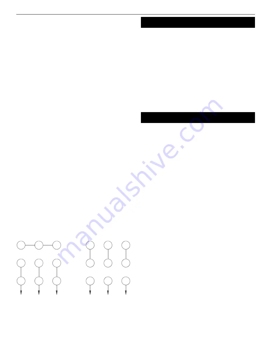
Grinder is prewired at the factory for 220 volt, 3-phase
operation. See Figure 2 for wiring diagram.
•
Grinder can be wired for 440 volt, 3-phase operation.
See Figure 2 for wiring diagram for 440 volt.
•
Test grinder to be sure grinding wheels rotate downward
toward tool rests. Switch any two leads to reverse rotation
if needed.
OPERATION
WARNING:
Always wear safety glasses complying with United
States ANSI Z87.1 (shown on package) before commencing power
tool operation.
•
Keep a steady, moderate pressure on the work and keep it
moving at an even pace for smooth grinding.
•
Pressing too hard overheats the motor and prematurely wears
down the grinding wheels.
•
Note the original bevel angle on the item to be sharpened and
try to maintain that angle. Sharpening a cutting edge requires
removing burrs from edge.
•
Deburring edge is done best by using the grinder to pull burr
from edge across the bevel angle.
•
The grinding wheel should rotate into object being sharpened.
•
Dip work into a coolant regularly to prevent overheating.
Overheating can weaken metals.
MAINTENANCE
•
As wheels wear, tool rests should be positioned closer to the
face of the wheels.
•
The gap between the wheel and the tool rest should not be
greater than
1
/
16
”. When the wheels are worn to the extent that
the
1
/
16
” maximum gap cannot be maintained, the wheels
should be replaced.
•
Replacement wheels should have a minimum rated speed of at
least 3600 RPM for 82082A and 1800 RPM for 82102A.
•
Maximum wheel diameter for 82082A is 8”, and 10” for 82102A.
•
To loosen nuts holding the wheels, disconnect power and push
a wood wedge between the tool rest and the wheel to keep
the shaft from turning. The threads on the right side of the
grinder (facing unit) are right hand; threads on the left side are
left hand. Tighten nuts securely before operating the grinder.
•
For grinding efficiency, wheels should be dressed periodically,
especially if they become clogged from grinding soft metals.
Palmgren Operating Manual & Parts List
82082A & 82102A
Figure 2 – Wiring Diagram
VOLTAGE CHANGE DIAGRAM
DISCONNECT FROM SUPPLY CIRCUIT BEFORE OPENING
220 VOLTS
440 VOLTS
4
1
7
8
2
3
9
6
5
4
1
7
8
2
3
9
6
5


