Palmgren 80161 Operating Manual & Parts List Download Page 5

5

Palmgren Operating Manual & Parts List

80161 & 70104

OPERATION (CONTINUED)

DEPTH STOP

Refer to Figures 6 and 7.

Repeated operations where depth of cut is consistent are made
easier by using depth scale (Figure 6, Ref. No. 47) and depth setting
knob (Figure 7, Ref. No. 9).

Depth of cut is shown on depth scale and indicated by depth indi-
cator (Figure 6, Ref. No. 48).

Depth of cut is set by rotating depth setting knob until desired
depth is obtained.

HANDWHEEL SCALES

Refer to Figure 8.

The cross feed handwheel and right-hand longitudinal handwheel
are equipped with graduated collars.

One full rotation of handwheel moves table .100”. Handwheel
scales are graduated in .001”.

Scales are used when precise movement of table is required.

Scales can be zeroed by loosening dial screw (Ref. No. 16) and
rotating lead screw dial (Ref. No. 13) until zero marks are aligned.

Tighten dial screw.

TABLE STOP BLOCKS

Refer to Figure 8.

Longitudinal travel can be limited to make repeated operations
easier by using the table stop blocks (Ref. No. 40).

Table stop blocks are positioned to contact table stop bracket (Ref.
No. 26) limiting table travel.

Adjust stop blocks by loosening socket head bolts (Ref. No. 39) and
moving stop blocks to desired position. Secure socket head bolts.

TABLE LOCKS

Refer to Figure 8.

Mill drill table can be locked into position using table lock handles
(Ref. No. 27).

Longitudinal position is secured by tightening lock handles on
front of saddle.

Cross feed position is secured by tightening lock handles on right
side of saddle.

REMOVE ARBOR

Loosen draw bar with wrench and remove arbor from spindle.

M

MA

AIIN

NT

TE

EN

NA

AN

NC

CE

E

Refer to Figures 5, 6, 7 and 8.

Keep all moving parts and surfaces clean of dirt, metal chips, etc.
Keep a light coating of oil on all exposed surfaces, including table
top and slots, all dovetail way surfaces, lead screws, rack and col-
umn.

Replace worn V-belts.

Check electrical connections and replace any worn or frayed wires
or line cords.

Replace worn way cover.

GIB ADJUSTMENT

Refer to Figures 5 and 8.

Palmgren mill drill is equipped with adjustable gibs (See Figure 5)
on longitudinal and cross feed that eliminate excess play in table
as dovetail ways wear over time.

Rotating gib adjustment bolts (Ref. No. 25) clockwise tightens
dovetail ways. Adjust gib bolts until a slight drag is felt when mov-
ing the table with handwheels. Loosen bolts if table is too tight.

REPLACE RETURN SPRING

Refer to Figure 6 and 7.

Return spring may wear after extended use and will need replace-
ment. If spindle does not return to full up position when released,
then replace return spring.

CAUTION:

Spring is under tension and may tend to twist forceful-

ly when relaxed.

To replace return spring, push spindle to fully up position and lock
it in place by tightening quill lock handle (Figure 7, Ref. No. 23).

Loosen spring cover knob (Figure 6, Ref. No. 38) slowly and careful-
ly rotate spring and cover clockwise to relax spring tension.

Remove spring cover knob and washer (Figure 6, Ref. No. 38 and
40). When tension is released, rotate spring and cover clockwise to
release spring from mounting screw.

Remove spring and cover. Place new spring over pinion shaft and
slide slot at end of spring over mounting screw. Press spring and
cover against head casting.

Replace washer and spring cover knob. Rotate cover counterclock-
wise to tension spring. Rotate cover approximately three full turns
and tighten cover knob. Release quill lock handle.

Test spring tension by pulling down on crank handle (Figure 6, Ref.
No. 19). Adjust spring tension as needed.

Overtightening spring causes quill to return with excessive
force damaging quill and rubber bumper (Figure 7, Ref. Nos. 5
and 19).

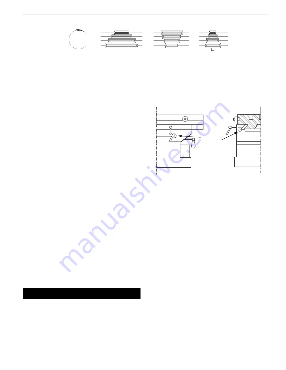
Figure 4 – Spindle Speed Chart

B

C

A

1

2

3

4

Motor

Spindle

Spindle
Rotation

D

X

Y

W

Z

Figure 5 – Gib Adjustment

Gib
Adjustment
Bolts

Summary of Contents for 80161

Page 1: ...a al l p pa ar rt ts s l li is st t 8 80 01 16 61 1 7 70 01 10 04 4 M MI IL LL L D DR RI IL LL L A AN ND D S ST TA AN ND D Read carefully and follow all safety rules and operating instructions before...

Page 2: ...phases of unpacking and installation Mill drill is shipped assembled except for certain parts shipped loose in a wooden box Locate and account for the following parts A Drill chuck arbor B 5 8 Drill...

Page 3: ...ving parts and cutting surfaces Never leave tool running unattended Turn the power off and do not leave tool until it comes to a complete stop Do not overreach Keep proper footing and balance Never st...

Page 4: ...ure 8 Ref No 6 does not bind Raise or lower head by turning head adjusting crank Figure 6 Ref No 34 Be sure to tighten both hex nuts after adjusting head CHANGING SPEED Palmgren mill drill is a 12 spe...

Page 5: ...lots all dovetail way surfaces lead screws rack and col umn Replace worn V belts Check electrical connections and replace any worn or frayed wires or line cords Replace worn way cover GIB ADJUSTMENT R...

Page 6: ...l if necessary WEEKLY Oil cross feed lead screw Figure 8 Ref No 20 Oil dovetail ways MONTHLY Oil handwheel bearings through oil fittings Figure 8 Ref No 19 Oil gear rack on back of quill where pinion...

Page 7: ...iod V belts loose 1 Spindle bearings loose 2 Table is loose 3 Worn spindle bearings 4 Head clamp bolts loose 1 Poorly adjusted return spring 2 Worn return spring Worn lead screw nuts 1 Loose spindle b...

Page 8: ...t 80161 Figure 6 Repair Parts Illustration for Head 35 36 34 33 32 31 29 28 27 60 59 30 37 55 54 53 52 38 44 25 24 23 18 22 21 20 16 15 14 11 8 4 6 3 5 12 13 10 9 8 7 63 2 1 50 64 49 48 47 46 57 51 42...

Page 9: ...00 1 30 Worm gear 05899 00 1 31 3 AMI 14 Retaining ring 05989 00 2 32 Worm gear shaft 16488 00 1 33 6 1 0 x 20mm Socket head bolt 4 Ref No Description Part No Qty 34 Head adjusting crank 05901 01 1 3...

Page 10: ...r Parts Illustration for Head 56 53 45 44 43 42 41 40 40 39 67 37 35 38 55 66 67 62 63 59 51 57 71 60 61 18 61 69 48 58 50 24 23 22 21 20 25 26 27 28 29 32 68 30 31 31 33 19 17 14 15 16 8 7 6 5 11 13...

Page 11: ...35 8 1 25 x 10mm Set screw 2 36 Motor pulley 05914 00 1 Ref No Description Part No Qty 37 V belt 05665 00 1 38 Motor and key 17206 00 1 39 Pulley cover 17166 00 1 40 16 2 0mm Hex nut 2 41 Transmittin...

Page 12: ...epair Parts Illustration for Base 1 20 17 17 18 17 17 11 11 12 12 14 14 13 19 16 15 47 26 21 30 30 48 24 10 25 25 31 44 43 24 27 27 38 31 29 28 31 36 23 45 22 24 19 13 48 11 12 32 30 40 39 42 19 47 33...

Page 13: ...x 20mm Socket head bolt 6 25 Gib adjustment bolt 17182 00 2 26 Table stop bracket 05939 00 1 Ref No Description Part No Qty 27 Table lock handle 15348 00 4 28 Way cover 05941 01 1 29 Lower cover plat...

Page 14: ...ist 80161 Figure 9 Repair Parts Illustration for Control Assembly 13 13 13 16 16 14 15 19 18 17 47 20 27 8 5 3 1 46 18 4 21 22 11 52 50 31 32 30 33 34 35 37 48 48 39 49 45 51 44 43 42 41 40 25 26 38 3...

Page 15: ...05968 00 1 27 6 1 0 x 12mm Pan head screw 2 28 Plate 17193 00 1 29 Terminal block 17194 00 1 Ref No Description Part No Qty 30 Fuse holder 17205 00 1 31 Plate 17195 09 1 32 Transformer 17196 00 1 33 R...

Page 16: ...1 25mm Hex nut 12 3 8mm Flat washer 24 4 8 1 25 x 25mm Hex head bolt 20 5 Support 15301 00 2 6 Right panel 15302 00 1 7 Right plate 15303 00 1 8 12 1 75 x 50mm Hex head bolt 4 9 Foot 15304 00 4 10 8...

Page 17: ...17 Service Record Palmgren Mill Drill and Mill Drill Stand Date Maintenance Performed Replacement Components Required Palmgren Operating Manual Parts List 80161 70104...

Page 18: ...18 Palmgren Operating Manual Parts List 80161 70104 NOTES...

Page 19: ...19 Palmgren Operating Manual Parts List 80161 70104 NOTES...

Page 20: ...free of charge To order parts for a non warranty repair please contact your preferred Palmgren distributor To obtain the names of Palmgren distributors or to arrange warranty return please call Palmgr...

Reviews: