


5
Palmgren Operating Manual & Parts List
80110A
OPERATION (CONTINUED)
•
On units equipped with the Laser-Guide attachment, repairs
shall only be carried out by the laser manufacturer or autho-
rized agent.
•
Laser Warning label: Max output <5mW DIODE LASER: 630-
660nm, Complies with 21CFR 1040.10 and 1040. 11.
ADUSTING THE LASER LINES
Refer to Figure 4.
Check the laser beam alignment to ensure the intersection of the
laser lines precisely at the spot where the drill bit meets the work-
piece. If it is not, the laser lines should be adjusted using the laser
adjustment knobs located on the opposite sides of the head
assembly.
•
Mark an “X” on a piece of scrap wood.
•
Insert a small drill bit into the chuck and align its tip to the
intersection of the lines of the “X”.
•
Secure the board to the table.
•
Turn on the laser and verify the laser lines align with the “X” on
the workpiece.
•
If the laser lines do not align, loosen knobs on each side of the
laser module and rotate the lasers until the lines meet in the
center of the “X”. Retighten the knobs to secure.
NOTE: Check and adjust the laser beam alignment every time the
drill press table is raised or lowered to a new position.
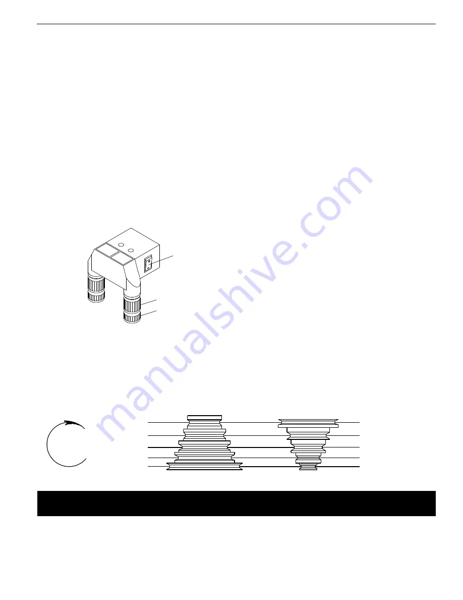
SPEED ADJUSTMENTS
Refer to Figures 5 and 7.
WARNING:
Be sure drill press is turned off and is disconnected
from power source before adjusting speeds.
•
To change spindle speed, loosen motor lock bolt (Ref. No. 5), on
the right side of the head and push the motor toward front of
drill press. This will loosen the belt and permit relocating the
belt to the desired pulley groove for the required spindle speed
(See Figure 5).
•
After belt has been repositioned, push motor mount plate (Ref.
No. 6) to move motor toward rear of drill press and tighten
motor lock bolt.
•
Check belt for proper tension and make any final adjustment. A
belt is properly tensioned when light pressure applied to mid-
point of the belt produces about 1/2” deflection.
TABLE ADJUSTMENTS
Refer to Figure 6.
•
Height adjustments: To adjust table, loosen locking handle (Ref.
No. 12) and turn crank handle (Ref. No. 7) to desired height.
Immediately retighten table bracket locking handle.
•
Rotation of work table : Loosen table locking handle (Ref. No.
12) and rotate table to desired position and retighten handle.
•
Tilting work table: Loosen hex head bolt (Ref. No. 13). Tilt table
to desired angle up to 45° and retighten hex head bolt.
•
To obtain more distance between chuck and table, the work
table can be rotated 180° and base can be used as a work sur-
face. This permits drilling of larger objects.
•
Clamp table securely after adjustments have been made.
DEPTH STOP ADJUSTMENT
Refer to Figure 7.
•
To control drilling depth, loosen locking bolt (Ref. No. 11) on
quill feed assembly (Ref. No. 10). Rotate scale so desired depth
is indicated on scale next to the pointer. Tighten locking bolt.
Use this feature to drill more than one hole to the same depth.
•
Spindle can be locked in either fully or partially down position.
Loosen locking bolt (Ref. No. 11). Lower chuck to desired depth,
rotate scale fully clockwise and tighten locking bolt. Use this
feature to set up and align work.
MOUNT DRILL BIT
WARNING:
Be sure drill press is turned off and is disconnected
from power source before adjusting speeds.
•
Place drill bit in jaws of drill chuck.
•
Tighten chuck with drill chuck key. Be sure to tighten the chuck
using all three key positions on the chuck body and remove
chuck key.
•
Use only the self-ejecting chuck key (Ref. No. 40) supplied with
this drill press, or a duplicate key. Use of any other key might
allow start up with the key still in the chuck. An airborne key
could strike the operator and cause injury.
Spindle
Rotation
Spindle
Motor
Figure 5 – Spindle Speed Adjustment
Recommended Drill Size per Material for 5 Speeds
5
4
3
2
1
5
4
3
2
1
5-5
4-4
3-3
2-2
1-1
3100
2340
1720
1100
620
in/mm
5/16 7.9
3/8
9.5
5/8 15.9
7/8 22.2
1
1
⁄
4
31.8
in/mm
3/16 4.8
1/4
6.4
3/8
9.5
1/2 12.7
3/4 19.0
in/mm
11/64
4.4
7/32
5.6
11/32
8.7
15/32 11.9
11/16 17.5
in/mm
5/32
4.0
3/16
4.8
5/16
7.9
7/16
11.1
5/8
15.9
in/mm
7/64
2.8
1/8
3.2
1/4
6.4
11/32
8.7
1/2
12.7
in/mm
3/32
2.4
3/32
2.4
5/32
4.0
1/4
6.4
3/8
9.5
in/mm
1/16
1.6
1/16
1.6
1/8
3.2
3/16
4.8
5/16
7.9
in/mm
1/32 0.8
3/64 1.2
1/16 1.6
1/8
3.2
1/4
6.4
Belt
Location
RPM
Wood
Zinc Diecast
Alum. &
Brass
Plastic
Cast Iron
& Bronze
Steel
Mild &
Malleable
Steel Cast &
Med.
Carbon
Steel
Stainless &
Tool
Figure 4 – Laser Guide Assembly
Laser
Knob
Switch


