background image

MR25661

18

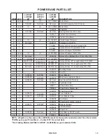
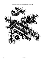
POWER RAKE

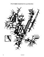
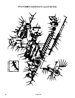
 PARTS ILLUSTRATION

90

91

95

94

93

68

92

95

96

94

59 23 35

5

59

55

50

50

52

55

59

47

56

2

45

55

70
34

26
27
36
37
66
37
36

27

31

55

45

61

63

41

39

40

42

64

33

58
32
21

29

49

28

50

1

55

59

46

55

59

59

55

3

15

13

22

8

8

14

66

30

69

6

71

38

7

43

57

38

43

20

48

60 19

49

75

72

44

73

74

58

54

51

67

12

10

11

4

9

24

25

65

62

68

53

17

18

16

Summary of Contents for FFC LAF5689

Page 1: ...Click Here To View Item at www GapPower com...

Page 2: ...States of America Copyright OPERATOR S AND PARTS MANUAL POWER RAKE SERIAL NUMBER ___________________ MODEL NUMBER ___________________ Manual Number MR25661 Models LAF5647 LAF5671 LAF5689 LAF5648 LAF56...

Page 3: ...Notes...

Page 4: ...7 SPECIFICATIONS 8 9 MOUNTING 10 HYDRAULIC CONNECTION 11 SET UP 12 OPERATION 13 MAINTENANCE 14 15 SERVICE 16 STORAGE 17 POWER RAKE PARTS ILLUSTRATION 18 20 22 POWER RAKE PARTS LIST 19 21 23 PTO POWER...

Page 5: ...d understand this manual If there is any portion of this manual or function you do not understand contact your local authorized dealer or manufacturer to obtain further assistance Keep this manual ava...

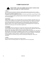
Page 6: ...to this equipment and the prime mover thoroughly before beginning installation operation or maintenance FOLLOW ALL SAFETY INSTRUCTIONS IN THIS MANUAL AND THE PRIME MOVER S MANUAL S READ AND UNDERSTAN...

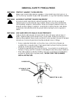
Page 7: ...when searching for hydraulic leaks DO NOT USE YOUR HANDS SEE ILLUSTRATION 4 76288 GENERAL SAfETy PRECAUTIONS WARNING PROTECT AGAINST fLyING DEbRIS always wear proper safety glasses goggles or a face s...

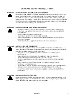
Page 8: ...ified by the tool manufacturer WARNING SAFELY OPERATE EQUIPMENT Do not operate equipment until you are completely trained by a qualified operator in how to use the controls know its capabilities dimen...

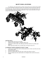
Page 9: ...legible Replace all missing illegible or damaged safety signs Replacement parts for parts with safety signs attached must also have safety signs attached Safety signs are available free of charge fro...

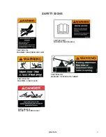
Page 10: ...5661 7 SAFETY SIGNS PART 50 10017 WARNING READ MANUAL PART 50 0724 WARNING HIGH PRESSURE FLUID PART RDL3314 DANGER ROTATING SHAFT PART RDL3100 WARNING STAND CLEAR PART RDL3123 WARNING PIVOTING ATTACHM...

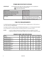
Page 11: ...ff PTO 540 rpm only The tractor must also provide for 3 point hitch attachment Category I or II The tractors rated drawbar PTO horsepower on a 3 point should be no less than 25 HP and no more than 100...

Page 12: ...MR25661 9...

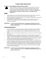
Page 13: ...nd all workers involved in the mounting process Making sure this product is in the operating position and level will facilitate in selecting the proper mounting holes 2 Read and understand the Operati...

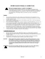
Page 14: ...a convenient steel surface in the cab of the prime mover If your unit is equipped with a quick connect wire harness for the prime mover joystick refer to owner s manual for proper installation and ope...

Page 15: ...deflector The gap should be consistent all across the deflector and this can be verified by either measuring or matching height marks on the two tabs that protrude up through a slot in the deflector...

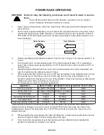
Page 16: ...ntain a consistent even grade 9 POWER RAKE OPERATION SAFETY FIRST READ AND UNDERSTAND THE SAFETY INSTRUCTIONS pages 2 5 of this manual BEFORE BEGINNING ANY POWER RAKE OPERATION WARNING Failure to obey...

Page 17: ...sure that tires are inflated to maximum load pressure indicated on tire Do not over inflate Make sure that all hydraulic fittings are tightened to specifications and that there are no leaks in any fit...

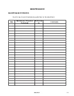
Page 18: ...MR25661 15 MAINTENANCE MAINTENANCE RECORD Use this log to record maintenance performed on the attachment Date Maintenance Procedure Performed Performed by Comments...

Page 19: ...disconnect the PTO driveline This should permit the roller to rotate freely 6 Pull the material from the roller while allowing it to rotate ALTERNATE METHOD FOR SKID STEER LOADERS If your prime mover...

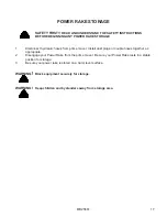
Page 20: ...s from prime mover Install dust plugs or couple hoses together as appropriate 2 Disengage your Power Rake from the prime mover Be sure your Power Rake rests in a stable position for storage 3 Be sure...

Page 21: ...35 5 59 55 50 50 52 55 59 47 56 2 45 55 70 34 26 27 36 37 66 37 36 27 31 55 45 61 63 41 39 40 42 64 33 58 32 21 29 49 28 50 1 55 59 46 55 59 59 55 3 15 13 22 8 8 14 66 30 69 6 71 38 7 43 57 38 43 20 4...

Page 22: ...12MB 17 2 Not Used LAF4657 48 LAF4682 57 Hydraulic Hose 5 x Length noted 10FJ 10FJ 18 2 Not Used LAF4682 57 LAF4709 66 Hydraulic Hose 5 x Length noted 10FJ 10FJ 19 1 LAF5600 Mounting Frame 20 1 LAF56...

Page 23: ...35 5 59 55 50 50 52 55 59 47 56 2 45 55 70 34 26 27 36 37 66 37 36 27 31 55 45 61 63 41 39 40 42 64 33 58 32 21 29 49 28 50 1 55 59 46 55 59 59 55 3 15 13 22 8 8 14 66 30 69 6 71 38 7 43 57 38 43 20 4...

Page 24: ...Grade 5 Lock Washer 31 55 40 P851108 Grade 5 Lock Washer 5 56 6 RHW6602 Not Used Not Used Grade 5 Lock Washer 63 for 48 model 57 2 RHW7003 Grade 5 Lock Nut 5 58 varies 13 19 25 RHW7101 Grade 5 Hex Nut...

Page 25: ...35 5 59 55 50 50 52 55 59 47 56 2 45 55 70 34 26 27 36 37 66 37 36 27 31 55 45 61 63 41 39 40 42 64 33 58 32 21 29 49 28 50 1 55 59 46 55 59 59 55 3 15 13 22 8 8 14 66 30 69 6 71 38 7 43 57 38 43 20 4...

Page 26: ...19 Link Arm 91 1 LAF5639 Mounting Frame 92 1 LAF5641 Back Plate 93 8 LAF5643 Bushing 94 8 P101020 Grade 5 Hex Head Cap Screw 63 x 5 95 8 RHW7603 Grade 5 Lock Nut 63 96 2 RHW8148 Clevis Pin 63 x 4 75 N...

Page 27: ...7 8 9 10 11 12 13 14 15 16 17 18 19 20 21 22 24 25 26 27 28 29 30 31 32 55 35 42 43 45 47 48 49 50 54 56 59 60 63 64 65 67 68 69 70 73 74 75 1 76 77 12 42 43 49 60 58 62 51 33 64 60 48 60 72 67 53 44...

Page 28: ...AF5692 LAF5634 LAF5627 Drum Deflector Strap 17 1 LAF5636 Left Side Shield 18 2 LAF5638 Wheel Post 19 1 LAF5644 Spur Gear Case 20 1 LAF5645 Bearing Assembly 21 1 LAF5646 90 Gear Box 22 1 07 10124 PTO D...

Page 29: ...7 8 9 10 11 12 13 14 15 16 17 18 19 20 21 22 24 25 26 27 28 29 30 31 32 55 35 42 43 45 47 48 49 50 54 56 59 60 63 64 65 67 68 69 70 73 74 75 1 76 77 12 42 43 49 60 58 62 51 33 64 60 48 60 72 67 53 44...

Page 30: ...ery Bushing 135 x 1 25 ID 58 varies 12 15 19 P851105 Grade 5 Lock Washer 31 59 7 P851106 Grade 5 Lock Washer 38 60 34 P851108 Grade 5 Lock Washer 5 61 2 RHW7003 Grade 5 Lock Nut 5 62 varies 9 9 12 RHW...

Page 31: ...7 8 9 10 11 12 13 14 15 16 17 18 19 20 21 22 24 25 26 27 28 29 30 31 32 55 35 42 43 45 47 48 49 50 54 56 59 60 63 64 65 67 68 69 70 73 74 75 1 76 77 12 42 43 49 60 58 62 51 33 64 60 48 60 72 67 53 44...

Page 32: ...QTY LAF5696 56 LAF5697 72 LAF5698 90 DESCRIPTION 80 1 LAF2818 Position Tube male 81 1 LAF2817 Position Tube female 82 1 RHW8133 Rue Ring Cotter Pin 5 Heavy 83 1 RHW8150 Clevis Pin 5 x 2 75 2 53 Usabl...

Page 33: ...ic Hose 5 x length noted 10FJ 10FJ 8 1 LAF9441 LAF9441 Wire Assembly 9 9 Contact FFC to obtain correct Wire Harness with Box for Rotating Cylinder 10 2 P100505 P100505 Grade 5 Hex Head Cap Screw 31 x...

Page 34: ...the option to repair or replace the product b Timely Repair and Notice In order to obtain the Limited Warranty i the product must be repaired within thirty 30 days from the date of failure and ii a cl...

Page 35: ......

Reviews: