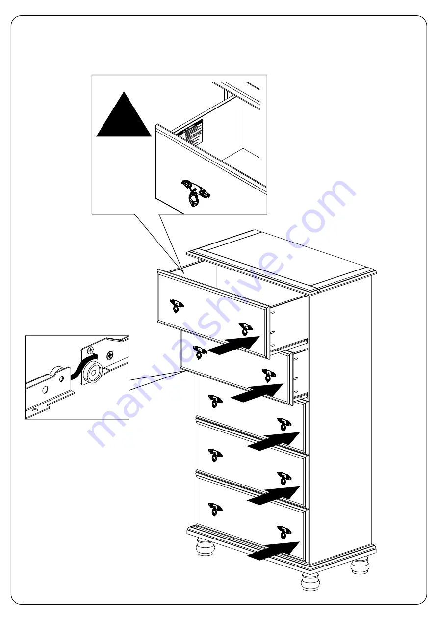
12)
D
rawer
with the WARNING label must be placed i
n the top position
page 14/15
!
Page 1: ...e of the product Our warranty is expressly limited to the replacement of furniture parts and components for one year following the date of purchase PALACE IMPORTS will replace any part that is defecti...
Page 2: ...ASSEMBLY GUIDE KYLE 5 DRAWER SUPER JUMBO CHEST SKU 8311 White SKU 8313 Mocha SKU 8316 Java PH 2 REV 10 2022 page 2 15 31 17 58...
Page 3: ...ts is provided below If any parts are missing or damaged please contact us at info palaceimportsinc com Assemble on a flat smooth surface on top of a blanket Use only low speed power drill setting Ass...
Page 4: ...1 4 0x14 B19 04 7 0x70 C2 56 3 8 0x25 E1 05 E2 05 G3 01 FURNITURE TIPOVER CAN RESULT IN SERIOUS INJURY OR DEATH This chest includes tipover prevention hardware that MUST BE ATTACHED TO THE WALL per t...
Page 5: ...01 C2 8 0x25 56 C2 07 C2 C2 C2 C2 C2 C2 C2 C2 C2 C2 08 17 16 C2 C2 C2 5x C2 C2 C2 10 C2 C2 C2 C2 4x page 5 15...
Page 6: ...FINISHED FRONT B31 6 0x10 15 E1 05 RIGHT Side E1 B31 08 B31B31 E1 B31 B31B31 E1 B31 B31B31 E1 B31 B31B31 E1 B31 B31B31 05 Glide wheels should be positioned towards the front and bottom of the side pan...
Page 7: ...CK TOP BOTTOM FINISHED FRONT B31 6 0x10 15 E2 05 RIGHT Side 07 B31 B31 B31 B31 B31 B31 B31 B31 B31 B31 B31 B31 B31 B31 B31 page 7 15 Glide wheels should be positioned towards the front and bottom of t...
Page 8: ...04 A1 4 0x30 04 A1 4 0x30 03 05 A1 12 07 12 07 A1 A1 A1 A1 12 07 10 10 10 10 A1 A1 A1 A1 page 8 15...
Page 9: ...06 A1 4 0x30 07 07 A1 12 08 A1 12 08 A1 A1 A1 A1 A1 A1 11 A16 A16 4 0x40 06 10 10 10 10 12 08 11 A16 A16 A16 A16 A16 A16 page 9 15...
Page 10: ...08 G3 01 B19 7 0x70 04 B19 11 13 13 G3 11 13 B19 G3 13 13 B19 G3 page 10 15...
Page 11: ...x30 02 G1 10x10 40 G1 G1 G1 G1 G1 G1 G1 G1 G1 G1 G1 G1 15 G1 G1 G1 15 15 A1 4 4 15 15 A1 A1 4 4 21 A1 G1 G1 G1 G1 G1 G1 G1 G1 G1 G1 G1 G1 G1 G1 G1 G1 G1 G1 G1 G1 G1 G1 G1 G1 G1 G1 G1 G1 page 11 15 FLU...
Page 12: ...10 A1 17 16 05 20 03 A1 4 0x30 60 A1 A1 05 17 16 20 A1 A1 A7 05 5x H20 10 A7 3 0x16 20 A7 H20 05 A7 H20 A7 A1 A1 A1 A1 A1 A1 page 12 15 A7 A7 H20...
Page 13: ...11 5x A42 20 4 0x14 E1 330mm 13 05 E2 05 330mm 13 E1 E1 E2 E2 Flip the assembled drawer UPSIDE DOWN to install glides E1 A42 05 E2 A42 A42 A42 A42 E1 A42 A42 E2 A42 page 13 15 BOTTOM...
Page 14: ...12 Drawer with the WARNING label must be placed in the top position page 14 15...
Page 15: ...TIPOVER PREVENTION KIT INSTALLATION Attach to chest A8 A8 F8 F8 Anchors and screws not included Screw into drywall F9 DRYWALL DRYWALL Install both parts F8 Tether and tighten F8 F9 01 F8 02 A8 3 0x20...