background image

33

GTV


FORCED CONVECTION AIR HEATERS   

Instructions for Installation and Servicing

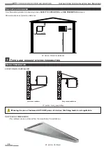
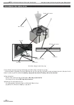
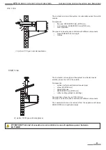
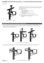
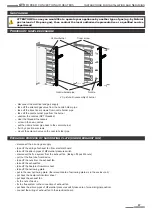
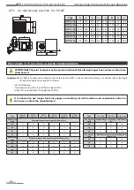
The minimum distance of the flue and air supply system from the roof at C32 type 

38. picture: Minimum distances at C32 type

min. 800

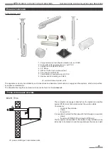
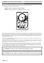
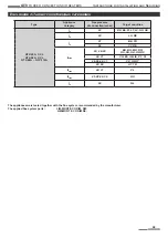
These components are optional accessories of GTV-CL-type appliances according to the Fig 30/a,b� If you would like to purchase 

these air duct components, please contact with sales section of PAKOLE  TRADE Ltd�

8.


Accessories

T form with „winter-sum-

mer” mode relay

(TIK…)

Outside air sucking form 

with bird protector grid

(KLM...)

Filter keeping with 

filter 

 (SZTS…)

Vibration damper

 (RT…)

Fire damper

(TCS…)

Adjustable straight air 

channel section (AEL…)

40. picture: Air duct components

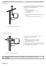
Type

Marking

(mm)

m

TIK...

50

KLM���

-

SZTS���

150

RT���

160

TCS���

a

AEL���

500

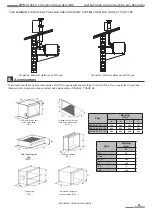
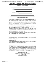
Type

Marking

(mm)

a

b

c

d

GTV-20���27 A / C / CL

350

600

350

500

GTV-33���40 A / C / CL

500

600

400

550

GTV-48���58 A / C / CL

650

600

450

600

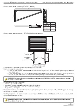
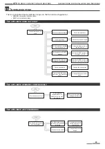
min. 800

39. picture: Minimum distances at C52 type

Summary of Contents for GTV-107A

Page 1: ...NE OR NATURAL GAS FIRED GTV TYPE WARM AIR BLOWERS Instructions for Installation and Servicing GTV 68A GTV 78A GTV 87A GTV 97A GTV 107A GTV 116A Appliance types GTV 20A C CL GTV 27A C CL GTV 33A C CL G...

Page 2: ...lation 11 Appliance installation 11 Gas connection 11 Electrical connection 12 Connection cable data 12 Electrical connection 13 Optional accessories 24 Electrical connecting specification 24 Regulati...

Page 3: ...his Instruction for Installation and Servicing can cause seri ous bodily injuries or damages as follows burning explosion suffocation carbon monoxide poisoning electric shock and in extreme case death...

Page 4: ...and fan coil units Text with EEA relevance C 2016 7769 for start up operation and use solely under legal conditions permitted under Article 1 2 m point of this Regulation Article 1 Subject matter and...

Page 5: ...animals from the equipment Never service mend such devices which are hot and during operation or electrical charged Never mount such air duct unit on front or back side of device which is not approve...

Page 6: ...inside the unit Beware of roof corners of outdoor units Keep suction grids always clear Before cleaning or maintaining the unit make sure that all electrical parts have been switched off the applianc...

Page 7: ...ght There is an envelope inside the unit containing the Instructions for Installation and Servicing User s Guide use and Guarantee and ser vices and the warranty documents The appliance operates based...

Page 8: ...ger Isolation Temperature limiter Exhaust chamber Flue gasket Magnetic valve Differential air pressure switch Electronic controller Partition plate Dual thermostat Exhaust gas narrowing Exhaust fan Co...

Page 9: ...r leading Device side sheet Air leading lamella Device bottom cover Air leading Device door Combustion air connection Axial or centrifugal blower fan Flue connec tion Device cover Blower fan Flue con...

Page 10: ...ir leading lamellas or through the attached air duct to the demanded places 5 picture Axial fan type warm air blower 6 picture Centrifugal fan type with lamella execution Features suction in of heater...

Page 11: ...In case of unique solution namely there is pressure regulator before each appliance before every pressure regulator in case of centrally mounted pressure regulator before pressure regulator and each a...

Page 12: ...and close the gas valve front of the burner The appliance must be connected to a grounded power sup ply system If the above instructions are not followed that can lead to death heavy injuries or prope...

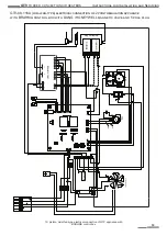
Page 13: ...LL M gnesszelep Connect the heater electrically according to the attached drawing Electrical connection scheme might be changing we do recommend using the electrical wir ing scheme sent with the produ...

Page 14: ...60 80 C F stg z ventil tor Lfv Axi l ventil tor N L N V L 11 4 3 2 1 7 5 9 10 12 25 24 23 22 21 20 19 18 17 16 15 14 13 32 31 30 L N L1 Burkolat 26 M gnesszelep SIT 579 DBC GTV 20 58A axial fan type...

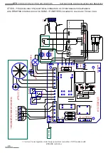
Page 15: ...4 3 2 1 7 5 9 10 12 25 24 23 22 21 20 19 18 17 16 15 14 13 32 31 30 N L Centrifug l leveg ramoltat ventil tor 1 3 2 4 A1 A2 26 Burkolat REJTS EL M gnesszelep VK4125C1007 M gnesszelep HONEYWELL GTV 20...

Page 16: ...32 31 30 N L Centrifug l leveg ramoltat ventil tor 1 3 2 4 A1 A2 26 Burkolat 11 4 3 2 1 6 7 5 9 10 8 12 11 4 3 2 1 7 5 9 10 12 REJTS EL M gnesszelep SIT840 SIGMA Elektronika SIT 579 DBC 405 M gnesszel...

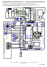
Page 17: ...l ventil tor N L N V L N 13 14 15 16 17 18 19 20 21 22 23 24 25 11 4 3 2 6 7 5 9 10 8 12 11 4 3 2 1 7 5 9 10 12 1 26 Burkolat L N L1 L2 L2 REJTS EL M gnesszelep HONEYWELL GTV 20 78A Axial fan type ele...

Page 18: ...til tor N L V N L V N L N V L N 13 14 15 16 17 18 19 20 21 22 23 24 25 11 4 3 2 6 7 5 9 10 8 12 11 4 3 2 1 7 5 9 10 12 1 26 Burkolat L2 REJTS EL M gnesszelep VK4125C1007 M gnesszelep HONEYWELL L2 GTV...

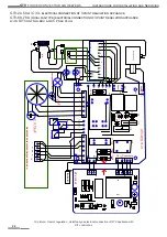
Page 19: ...29 12 13 14 15 16 17 18 19 20 21 C Piros Z ld L N L1 15 14 13 12 11 10 9 8 7 6 5 4 3 2 1 JT2 JT1 J6 J5 DUNGS HONEYWELL Burkolat BRAHMA CM31 A1 A2 1 3 2 4 REJTS EL M gnesszelep GTV 68 116A Axial fan ty...

Page 20: ...RM FAN TERM BIZT TERM K sz l k burkolat n helyezkednek el 15 14 13 12 11 10 9 8 7 6 5 4 3 2 1 JT2 JT1 J6 J5 BRAHMA CM31 DUNGS HONEYWELL Burkolat M gnesszelep GTV 68 116A Axial fan type electrical conn...

Page 21: ...eset Szelep OUT Szelep IN LIMIT TERM FAN TERM BIZT TERM K sz l k burkolat n helyezkednek el SIT 579 DBC REJTS EL M gnesszelep Seg dszelep GTV 20 58A C CL electrical connection of 2 point regulation ap...

Page 22: ...p IN LIMIT TERM FAN TERM BIZT TERM K sz l k burkolat n helyezkednek el Burkolat REJTS EL M gnesszelep VK4605A1096 MBC 120 Elektronika BRAHMA CM31 SIT 579 DBC 405 M gnesszelep Seg dszelep GTV 20 58A C...

Page 23: ...1 IN 4 5VDC 230VAC 12VAC OUT Z M 18 V2 PAKOLE Trade Ny1 R9 C7 D4 D5 L1 T3 IC1 T2 C5 C6 R8 C E B C 3 15uF GTV MOD 18 V4 Z ld Piros F g z ventil tor ION Elektronika Reset Szelep OUT Szelep IN LIMIT TERM...

Page 24: ...ay The appliance can not be attached to the mains by plug The proper installation of phase null wires have to be thoroughly checked The appliance has I class protection against electric shock for this...

Page 25: ...system If the appliance uses indoor air than need replace the air by ventilation 6 Appliance specification Ventilation This type of control is the so called PILOT control at which the communication be...

Page 26: ...FETY OF OPERATION and FIRE PREVENTION distances Minimal dimensions of protective distances Protective distances 24 picture Protective distances Location on cantilever 7 Fixing and exhaust system possi...

Page 27: ...posed drilling through of wall and mounting with over lap WARNING Before installation of appliances between 68 116KW the STATIC investigation of walling is in any case needed Proposed installation mod...

Page 28: ...r and plastic inserted self locking nut must be mounted Suspension type installation Further instructions between the riveted nuts and bracket plates be M16 large sized washer the srewes be mounted wi...

Page 29: ...ly is directly from the heated area and flue system 100 mm is horizontally across the wall to outside Components horizontal flue terminal clamp flue pipe 1 m It is possible to extend the flue pipe wit...

Page 30: ...ed 150 100 mm Components vertical flue roof terminal flue pipe 250 500 1000 mm 100 mm elbow 90 100 mm rubber sealing It is possible to extend the flue pipe with the following components clamp flue pip...

Page 31: ...f terminal fume air coaxial pipe elbow 90 100 mm straight line pipe 250 500 1000 mm 100 mm rubber sealing straight or slanting The pipe diam above the roof 100 150 mm The pipes can be extended or shor...

Page 32: ...ing air supply pipe 250 500 1000mm 150 mm cover The pipes can be extended or shorted with different components pipes 250 500 1000 mm 100 mm clamps 35 picture C52 type execution The combustion air supp...

Page 33: ...t components please contact with sales section of PAKOLE TRADE Ltd 8 Accessories T form with winter sum mer mode relay TIK Outside air sucking form with bird protector grid KLM Filter keeping with fil...

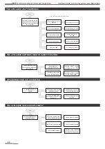
Page 34: ...the tem perature regulator General information The flame detector is self checking and can just operate with the burner other environmental effects ambient temperature lights can not influence it 9 A...

Page 35: ...e at minimum pressure After that set the room temperature value The GTV type warm air blowers apart from the checking of suspension and cleaning of cover lamellas and circulating fan do not need extra...

Page 36: ...if necessary clean those supervision of the quality of combustion dismounting and clean of the gas filter by high pressure air ATTENTION After every maintenance the appliance must be again adjusted C...

Page 37: ...cs tinner screws mount the solenoid valve on the nozzle holder pipe disconnect the air and gas supply take off the wiring of exhaust fan from electrical board take off the silicon pipes of differentia...

Page 38: ...eases under the LIMIT OFF the elec tronic control starts the burner again The values of the combined thermostat is adjusted by the manufacturer so not necessary to modify the values Only authorized ex...

Page 39: ...Raise the temperature on the thermostat The device is in RESET position Push the RESET button on the therm or PCB The safety temperature lim iter therm is switched off Push the RESET button on the tem...

Page 40: ...s no gas Check the gas pressure In case of only Honeywell electronic control The appliance switches over to safety position dur ing operation Interrupted gas supply continuous Push the RESET button on...

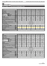
Page 41: ...OD Electrical connection 230V 50Hz Nominal current consumption A 0 9 0 9 1 77 1 77 1 9 1 9 Electrical performance W 219 239 416 455 437 610 Noise level dB A 53 53 55 55 55 57 Weight kg 65 5 83 5 95 IP...

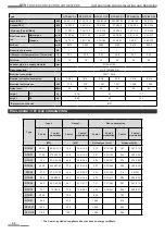
Page 42: ...5 48 78 9 9 06 7 05 GTV 97 98 9 91 0 10 48 8 16 GTV 107 103 4 95 2 10 95 8 53 GTV 116 118 8 109 1 12 58 9 80 Type GTV 20C CL GTV 27C CL GTV 33C CL GTV 40C CL GTV 48C CL GTV 58C CL Input NCV kW 20 25 1...

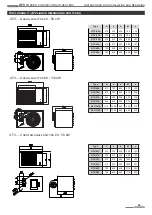
Page 43: ...0 135 GTV 33A 610 510 625 805 187 GTV 40A 610 510 625 805 187 GTV 48A 750 650 625 805 252 GTV 58A 750 650 625 805 252 Type A a b M e GTV 68A 810 700 840 970 238 GTV 78A 810 700 840 970 238 GTV 87A 960...

Page 44: ...e more elbows you need to reduce the length of fresh air supply and venting set as follow It is allowed to use longer fresh air supply and venting set with isolation and condensate outlet In this case...

Page 45: ...K EE FI LT LV NO SE I2E 20 LU DE I3P 37 BE FR 50 CY DE II2H3P 20 28 30 BA BG MD RO RU SK UA HR RS 20 37 CH ES GB IE PT SI 20 28 30 37 CZ GR IT 20 50 AT TR II2E3P 20 37 PL II2H3P 25 28 30 50 HU I3P 50...

Page 46: ...by not authorized retailer or service station The regular maintenance is the owner s responsibility The manufacturer does not assume the responsibility in case of accidentally happened or directly cau...

Page 47: ...47 GTV FORCED CONVECTION AIR HEATERS Instructions for Installation and Servicing...

Page 48: ...PAKOLE TRADE Ipari s Kereskedelmi Kft H 8000 Sz kesfeh rv r B rg ndi t 8 10 Web www pakole hu E mail mail pakole hu Tel 36 22 316 484 www pakole com...

Reviews: