


8.
2D
‐
DNR
(2D
Noise
Reduction)
‐
LOW
‐
MIDDLE
‐
HIGH
‐
DISABLED:
Deactivates
2DNR.
Noise
is
not
reduced.
‐
OFF
:
Activates
2DNR(Level
:
0).
Noise
is
not
reduced.
Note
<Bad
pixel
detection
>
function
is
operated
only
when
<2D
‐
DNR
DISABLED
>
is
selected.
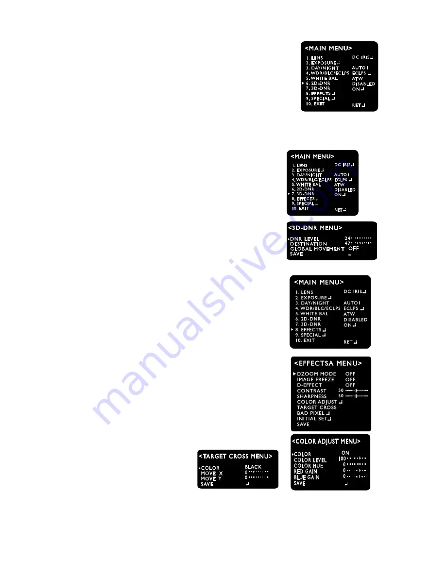
9.
3D
‐
DNR
(3D
Noise
Reduction)
The
background
noise
in
the
low
light
level
decreases
automatically
as
the
level
of
gain
changes.
‐
DNR
LEVEL
Adjust
the
noise
reduction
level.
‐
DESTINATION
Adjust
the
3DNR
gain.
‐
GLOBAL
MOVEMENT
Control
ghost
phenomenon
10.
EFFECTS
‐
D
‐
ZOOM
:
You
can
use
a
digital
zoom.
∙
ZOOM
:
x1
~
x8.30
∙
DZOOM
PAN
:
‐
100
~
100
∙
DZOOM
TILT
:
‐
100
~
100
‐
IMAGE
FREEZE
:
You
can
view
still
or
live
image.
‐
D
‐
EFFECT
∙
V
‐
FLIP
:
You
can
flip
the
picture
vertically
on
the
screen.
∙
MIRROR
:
You
can
flip
the
picture
horizontally
on
the
screen.
∙
ROTATE
:
You
can
flip
the
picture
rotatively
on
the
screen.
‐
CONTRAST
:
0
~
100
‐
SHARPNESS
:
0
~
100
‐
COLOR
ADJUST
∙
COLOR
:
ON/OFF
∙
COLOR
LEVEL
:
0
~
200
.
COLOR
HUE
:
‐
180
~
180
.
RED
GAIN
:
‐
100
~
100
.
BLUE
GAIN
:
‐
100
~
100
‐
TARGET
CROSS
:
Display
‘
╇
’
on
the
screen
∙
COLOR
:
BALCK,GRAY,WHITE,RED,GREEN,YELLOW
∙
MOVE
X
:
‐
100
~
100
.
MOVE
Y:
‐
100
~
100
.
INITIAL
SET
.
SAVE
Note
At
TARGET
CROSS
function
is
in
operation,
‘
╇
’
display
shall
disappear
if
MOTION
DET
function
is
‘ON’
19 version 1.0.1


