background image

2

Packard Bell Vibe 300 Disassembly Manual

Overview

This document contains step-by-step disassembly instructions for the Vibe 300 MP3 player. The
instructions are illustrated where necessary with images of the part that is being removed or
disassembled.

Packard Bell reserves the right to make changes to the Vibe 300 MP3 player without notice.

Technician Notes

Only technicians authorized by NEC Computers International B.V. should attempt to repair this
equipment. All troubleshooting and repair procedures are detailed to allow only subassembly/module
level repair. Because of the complexity of the individual boards and subassemblies, no one should
attempt to make repairs at the component level or to make modifications to any printed wiring board.
Improper repairs can create a safety hazard. Any indication of component replacement or printed wiring
board modifications may void any warranty or exchange allowances.

Disassembly Instructions

When disassembling the unit, follow these general rules:

n

Turn off the power and disconnect all cables.

n

Label all removed connectors. Note where the connector goes and in what position it was
installed.

n

Do not disassemble the unit into parts that are smaller than those specified in the instructions.

Reassembly Instructions

Reassembly is the reverse of the disassembly process. Use care to ensure that all cables and screws are
returned to their proper positions. Check that no tools or any loose parts have been left inside the MP3
player. Check that everything is properly installed and tightened.

Required Tools

All disassembly procedures can be performed using the following tools:

n

Phillips (#1 bit) screwdriver

n

Small flat blade screwdriver

Summary of Contents for Vibe 300

Page 1: ...Packard Bell Vibe 300 Disassembly Manual ...

Page 2: ...nts Overview 2 Technician Notes 2 Disassembly Instructions 2 Reassembly Instructions 2 Required Tools 2 Removing the Bottom Cover 3 Removing the HDD 4 Removing the Battery 4 Removing the Main Board LCD Panel 5 Removing the Keypad 7 Reassembly Notes 7 Notice 9 ...

Page 3: ...g board Improper repairs can create a safety hazard Any indication of component replacement or printed wiring board modifications may void any warranty or exchange allowances Disassembly Instructions When disassembling the unit follow these general rules n Turn off the power and disconnect all cables n Label all removed connectors Note where the connector goes and in what position it was installed...

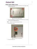
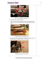
Page 4: ...er located on the FM module cover Fig 1 Removing the rubber stoppers 2 Remove the FM Module cover It has been clicked into place so you can easily push it out using a flat blade screwdriver Note Optionally remove the FM module clicked into the slot 3 Remove the four screws Fig 2 Screw in FM module compartment 4 Remove the bottom cover ...

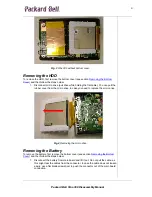
Page 5: ...ber cover from the micro drive in case you need to replace the micro drive Fig 4 Removing the micro drive Removing the Battery To remove the battery first remove the bottom cover see section Removing the Bottom Cover and then follow the steps below 1 Disconnect the battery from main board and lift it out Do not pull the cable as this might tear the cables from the connector In case the cable does ...

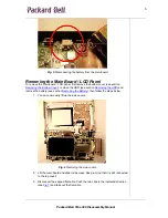
Page 6: ...over remove the HDD see section Removing the HDD and remove the battery see section Removing the Battery then follow the steps below 1 You can now easily lift up the side covers Fig 6 Removing the side covers 2 Lift the main board and slide it side ways Keep in mind that it is still connected to the top cover 3 Disconnect the keypad flat cable Push the two clips in the indicated direction see Fig ...

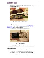
Page 7: ...eplace the main board disconnect the HDD flat cable Push the two clips in the indicated direction see Fig 8 and take out the flat cable Fig 8 Disconnecting the HDD flat cable 6 Disconnect the LCD flat cable from the main board Push the two clips in the indicated direction see Fig 9 and take out the flat cable Fig 9 Disconnecting the LCD flat cable ...

Page 8: ... panel see section Removing the Main Board LCD Panel then follow the steps below 1 Pull up the metallic tape covering the keypad and lift out the keypad Fig 11 Lifting keypad cover Note The keypad might have been glued to the top cover Use a flat blade screwdriver to leverage it gently Reassembly Notes Please pay attention to the following points during the re assembly of the unit n When placing b...

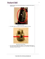
Page 9: ... the side panel Fig 12 Power button n The rubber stoppers are keyed so they only fit properly in one way Fig 13 Keyed rubber stopper n The micro drive is not keyed and therefore it can be inserted up side down In case you connect the drive the wrong way around you will see on the display the hard disk symbol with a red cross ...

Page 10: ... INTERNATIONAL B V SHALL NOT BE LIABLE FOR TECHNICAL OR EDITORIAL ERRORS OR OMISSIONS CONTAINED HEREIN NOR FOR INCIDENTAL OR CONSEQUENTIAL DAMAGES RESULTING FROM THE FURNISHING PERFORMANCE OR USE OF THIS MATERIAL Copyright 2005 NEC Computers International B V All rights reserved Packard Bell is a trademark of NEC Computers International B V Vibe 300 Disassembly Manual Author Product Support Consum...

Reviews: