background image

58

Packard Bell oneTwo M3600 AIO Computer Service Guide

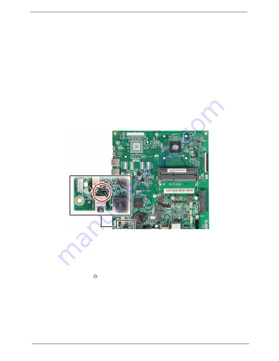
Clearing CMOS

You may need to clear the Setup configuration values (CMOS) if the configuration has been corrupted, or if 
incorrect settings made in the Setup Utility caused error messages to be unreadable. This procedure will clear 
the BIOS supervisor password as well. 

Use the CMOS1 jumper to clear the CMOS data. 

1-2 position: Normal operation (default)

2-3 position: Clear CMOS data

To clear the CMOS data:

1.

Turn off the power to the computer and all peripherals.

2.

Unplug the power cord from the computer.

3.

Unplug the network cable and all connected peripheral devices from the computer.

4.

Place the computer on a flat, steady surface with the rear cover facing upward.

5.

Remove the LCD assembly by following the procedure described on the page 30.

6.

Locate the CMOS1 jumper on the mainboard.

7.

Remove the jumper block and set it over the 2-3 pins for 20 to 30 seconds. 

8.

Return the jumper block to its default 1-2 position.

9.

Reinstall all assemblies or cables that have previously been removed.

10.

Reinstall the LCD assembly, front bezel, side bars and the computer stand.

11.

Connect the AC power cord to the system.

12.

Press the power button

 to turn on the computer. 

13.

During POST, press 

Delete

 to access the Setup Utility. 

14.

Press 

F9

 to load the system default values.

15.

Press 

F10

 to save the changes you made and close the Setup Utility.

Summary of Contents for oneTwo M3600

Page 1: ...Packard Bell oneTwo M3600 All In One Computer Service Guide PRINTED IN TAIWAN Service guide files and updates are available on the Acer CSD web site for more information go to http csd acer com tw ...

Page 2: ...rd Bell oneTwo M3600 AIO Computer Service Guide Revision History Refer to the table below for changes made on this version of the Packard Bell oneTwo M3600 All In One Computer Service Guide Date Chapter Updates ...

Page 3: ...rporated makes no representations or warranties either expressed or implied with respect to the contents hereof and specifically disclaims any warranties of merchantability or fitness for any particular purpose Any Acer Incorporated software described in this guide is sold or licensed as is Should the programs prove defective following their purchase the buyer and not Acer Incorporated its distrib...

Page 4: ...that appear on screen NOTE Gives additional information related to the current topic WARNING Alerts you to any physical risk or system damage that might result from doing or not doing specific actions CAUTION Gives precautionary measures to avoid possible hardware or software problems IMPORTANT Reminds you to do specific actions relevant to the accomplishment of procedures ...

Page 5: ...s generic service guide In such cases please contact your regional offices or the responsible personnel channel to provide you with further technical details FRU Information Please note WHEN ORDERING FRU PARTS that you should check the most up to date information available on your regional web or channel If for whatever reason a part number change is made it will not be noted in the printed servic...

Page 6: ...vi Packard Bell oneTwo M3600 AIO Computer Service Guide ...

Page 7: ...y 10 Navigating through the Setup Utility 11 Setup Utility Menus 11 Chapter 3 System Disassembly 25 Disassembly Tools 25 Pre disassembly Procedure 25 Disassembly Procedures 26 Removing the Computer Stand 26 Removing the Side Bars 27 Removing the Front Bezel 28 Removing the Webcam Module 29 Removing the LCD Assembly 30 Removing the LCD LVDS Cable 31 Removing the LCD Panel Bracket and Inverter Board...

Page 8: ...cators 48 BIOS Recovery 57 Clearing CMOS 58 Chapter 5 System Architecture 59 Block Diagram 59 Mainboard Layout 60 Chapter 6 Field Replaceable Unit FRU List 63 Exploded Diagram 64 FRU List 65 Appendix A Model Definitions and Configurations 71 Appendix B Test Compatible Components 73 Approved Vendor List AVL 75 Appendix C Online Support Information 79 Index 81 Table of Contents ...

Page 9: ...High Definition Audio Codec with Embedded Class D Speaker Amplifier I O ports Side panel USB ports two Headphone jack Microphone jack Rear panel Line out jack USB ports three Ethernet jack RJ 45 PS 2 keyboard and mouse ports Media storage 2 5 inch 5400 rpm SATA hard disk drive HDD Slim type SATA tray type or slot in optical disc drive ODD Card reader 4 in 1 card reader slot Supports MultiMediaCard...

Page 10: ...monitor Kensington lock Power management ACPI 2 0 compliant Energy Star 5 0 compliant Aspect Description System dimension W H D 61 5 484 402 5 mm 2 42 19 05 15 85 in Mainboard form factor Standard DTX Mainboard dimensions W H 190 175 mm Aspect Description Operating temperature 5 to 35 C 41 to 95 F Operating humidity 15 to 80 RH non condensing Component Description ...

Page 11: ... pictures and tables in this section illustrate the physical outlook of the computer Front View Item Component 1 Integrated webcam 2 Integrated microphone 3 Display screen 4 Speakers 5 Power button indicator Green System is in power on mode Amber System is in standby mode ...

Page 12: ...rd Bell oneTwo M3600 AIO Computer Service Guide Right Views Item Component 1 Increase brightness key 2 Decrease brightness key 3 USB ports 4 4 in 1 card reader 5 Microphone jack 6 Headphone jack 7 Reset button ...

Page 13: ...t and Rear Views Item Component 1 Ventilation slots 2 Mounting holes for wall mount option 3 Optical disc drive ODD 4 Kensington lock slot 5 Computer stand 6 Power jack 7 Ethernet port RJ 45 8 USB ports 9 PS 2 mouse port 10 PS 2 keyboard port 11 Line out jack ...

Page 14: ...Express Chipset Super I O ITE 8757 Item Specification BIOS chip AMI BIOS Setup utility CMOS Setup Utility Item Specification Controller Integrated in the Intel processor Number of DIMM slot 2 Maximum memory 2 GB using two 2 GB modules Data rate 1333 MT s Supported capacities 1 or 2 GB DIMM type 240 pin DDR3 SO DIMM Supported brands ADATA Hynix Kingston Micron Unifosa Samsung Population rule You ca...

Page 15: ...rpm Item Specification Controller Integrated in the Intel NM10 Express Chipset Type DVD Super Multi double layer or Blu ray Disc combo drive option Form factor Slim type tray type or slot in Tray height mm 12 7 mm Interface SATA Supported models DVD Super Multi double layer drive HLDS GT31N PLDS DS 8A4SH Item Specification Controller Realtek RTS5159 Card Reader Supported cards MultiMediaCard MMC S...

Page 16: ...Park Orchid C04PL036H Item Specification Panel model LG LM185WH1 Screen size diagonal 18 5 inch Type TFT LCD Resolution 1366 768 Wide XGA Aspect ratio 16 9 Display colors 16 7M 6bit A FRC Brightness typical 250 nits Contrast ratio 1000 1 Viewing angle H V typical 170 160 Response time typical 5 ms Backlight CCFL Interface Single channel LVDS Dimension H V 430 4 254 6 mm Inverter board Darfon VZ 12...

Page 17: ... Setup message to make changes to the BIOS settings The Setup Utility loads the configuration values in a battery backed nonvolatile memory called CMOS RAM This memory area is not part of the system RAM which allows configuration data to be retained when power is turned off The values take effect when the system is booted POST uses these values to configure the hardware If the values and the actua...

Page 18: ... you will need to restart the computer Use the Up Down Left Right arrow keys to move between the menu options then press Enter to execute that option Some options lead to pop up dialog boxes that prompt you to verify that you wish to execute that option Other options lead to dialog boxes that prompt you for information Some options marked with a lead to submenus that enable you to change the value...

Page 19: ...uare brackets is user configurable Grayed out parameters are not user configurable for one of the following reasons The field value is auto configured or auto detected The field value is informational only The field is password protected Esc If you press this key On one of the primary menu screens the Exit menu displays On a submenu screen the previous screen displays When you are making selection...

Page 20: ...or Speed Speed of the processor installed on the system System Memory Size of system memory detected during boot up Product Name Official model name of the computer System Serial Number System serial number System BIOS Version Current system BIOS version BIOS Release Date Date when the CMOS setup utility was released Asset Tag Number System asset tag number ...

Page 21: ...ATA channels each channel allows one SATA device to be installed Press Enter to display the individual configuration screen of installed SATA drive s Halt On Determines whether the system will stop for an error during the POST Options include All Errors Any error detected will pause the system No Errors BIOS will ignore any errors detected during POST All but Keyboard If a keyboard error is detect...

Page 22: ...em in this order By default the computer searches for boot devices in the following order Hard disk Optical drive CD DVD Removable device Network boot LAN Hard Disk Drive Priority Press Enter to specify the boot device priority sequence for the installed hard drive s Optical Disk Drive Priority Press Enter to specify the boot device priority sequence for the installed optical drive Removable Devic...

Page 23: ...GB This is a workaround for the PCI hole or PCI memory hole which is a limitation of 32 bit hardware and 32 bit operating systems that causes a computer to appear to have less memory available than is physically installed Note This feature is useful for systems running on 64 bit OS and those 32 bit systems that support the Physical Address Extension method Enabled Disabled Video Memory Size Displa...

Page 24: ...t for a USB mouse and USB keyboard When enabled any attached USB mouse or USB keyboard can control the system even when there is no USB driver loaded onto the system Enabled Disabled USB Storage Emulation If set to Auto a USB devices with a capacity of equal or less than 2 GB will be emulated as a bootable floppy disk Auto Floppy Hard Disk Onboard Audio Controller Enables or disables the onboard a...

Page 25: ...to wake up from a power saving mode when the onboard LAN controller received a network message Enabled Disabled Wake Up by PS 2 KB Mouse Enables or disables the system to wake up from a power saving mode when a PS 2 keyboard or mouse is used Enabled Disabled Wake Up by USB KB Mouse Enables or disables the system to wake up from a power saving mode when a USB keyboard or mouse is used Enabled Disab...

Page 26: ...U Temperature System Temperature CPU Fan Speed System Fan Speed CPU Core 3 30V 5 00V 5VSB VBAT These items lets you monitor the parameters for critical voltages temperatures and fan speeds Smart Fan When enabled fan speed will speed up or slow down depending on the system temperature Enabled Disabled ...

Page 27: ...ld to Enabled to reduce this EMI level This reduces interference problems with other electronics in the area Note Remember to disable the Spread Spectrum feature if you are overclocking A slight jitter can introduce a temporary boost in clock speed causing the overclocked processor to lock up Enabled Disabled Processor Multiplier This field is only visible if an engineering processor installed It ...

Page 28: ...rget your password you may have to return your computer to your dealer to reset it Field Description Value Supervisor Password Displays the supervisor password status When set to Installed this password will allow the user to access and change all settings in the Setup Utility Installed Not Installed User Password Displays the user password status Only the following menus will be accessible when t...

Page 29: ...ry then press Enter You will be prompted to save the new password 5 Press Enter 6 Press F10 to save the password and close the Setup Utility To remove a system password 1 Select Change Supervisor Password or Change User Password then press Enter The password box appears 2 Type the original password then press Enter 3 Press Enter twice without entering anything in the new and confirm password field...

Page 30: ...default settings for all Setup parameters Keyboard shortcut F9 Perform the steps below to load the system default settings 1 Select Load Default Settings then press Enter You will be prompted to load the system defaults 2 Select OK then press Enter 3 Press F10 to save the changes you made and close the Setup Utility ...

Page 31: ...O Computer Service Guide 23 Save Exit Setup Execute this menu to save the changes made and closes the Setup Utility Keyboard shortcut F10 Exit Without Saving Execute this menu to closes the Setup Utility without making any changes ...

Page 32: ...24 Packard Bell oneTwo M3600 AIO Computer Service Guide ...

Page 33: ...teps listed below 1 Make sure that the optical disc drive and the card reader slot are empty 2 Turn off the power to the computer and all peripherals 3 Unplug the power cord from the computer 4 Unplug the network cable and all connected peripheral devices from the computer 5 Place the computer on a flat steady surface with the rear cover facing upward NOTES To reinstall the system components and a...

Page 34: ...Procedures Removing the Computer Stand 1 Perform the Pre disassembly Procedure on page 25 2 Remove the plastic shell covering the computer stand screws 3 Remove the screws securing the computer stand Quantity Color Torque Part Number 3 Chrome 4 0 0 3 kgf cm 86 00J97 668 ...

Page 35: ...uter Service Guide 27 4 Remove the computer stand Removing the Side Bars 1 Perform the Pre disassembly Procedure on page 25 2 Remove the screws securing the side bars Quantity Color Torque Part Number 2 Black 4 0 0 3 kgf cm 86 ZA324 8R0 ...

Page 36: ...hen detach the bars Removing the Front Bezel 1 Perform the Pre disassembly Procedure on page 25 2 Remove the side bars by following the procedure described on the previous section 3 Use a flat screwdriver to pry off the front bezel from the rear cover 4 Detach the front bezel from the rear cover and turn it over to access the webcam cable ...

Page 37: ... Removing the Webcam Module 1 Remove the front bezel by following the procedure described on the previous section 2 Disconnect the webcam cable from the webcam module 3 Push the tabs securing the webcam module 4 Remove the webcam module from the front bezel ...

Page 38: ... then disconnect the disconnect the webcam cable from the webcam module 2 Remove the screws securing the LCD assembly to the rear cover 3 Detach the LCD assembly from the rear cover and turn it over to access the LCD panel cables 4 Disconnect the LCD and inverter cables from the mainboard Quantity Color Torque Part Number 6 Black 4 0 0 3 kgf cm 86 ZA324 8R0 ...

Page 39: ... LCD board Removing the LCD Panel Bracket and Inverter Board 1 Remove the LCD assembly by following the procedure described on the page 30 2 Remove the screws securing the LCD panel and inverter board brackets 3 Detach the LCD panel bracket from the LCD panel then turn over the inverter board bracket to access the inverter board cables Quantity Color Torque Part Number 4 Chrome 4 0 0 3 kgf cm 86 0...

Page 40: ...ervice Guide 4 Disconnect the inverter board cables from the inverter board 5 Remove the screws securing the inverter board 6 Remove the inverter board cage from its bracket Quantity Color Torque Part Number 2 Chrome 4 5 0 3 kgf cm 86 7A554 6R0 ...

Page 41: ... the LCD assembly by following the procedure described on the page 30 2 Disconnect the ODD power and data cables from the mainboard then the ODD SATA cable from the ODD 3 Remove the screw securing the ODD bracket to the chassis Quantity Color Torque Part Number 1 Chrome 4 0 0 3 kgf cm 86 00K96 644 ...

Page 42: ...M3600 AIO Computer Service Guide 4 Slide the ODD out of the rear cover 5 Remove the screw securing the ODD bracket 6 Detach the ODD bezel from the module Quantity Color Torque Part Number 2 Chrome 2 0 0 2 kgf cm 86 00K77 223 ...

Page 43: ...sembly by following the procedure described on the page 30 2 Remove the screw securing the HDD cage to the chassis 3 Slide the HDD assembly towards the ODD area to disengage the cage s tabs from the chassis then remove the HDD assembly Quantity Color Torque Part Number 1 Chrome 4 5 0 3 kgf cm 86 00K96 644 ...

Page 44: ...e hard drive to its cage 5 Slide the hard drive out of its cage Removing the System Fan 1 Remove the LCD assembly by following the procedure described on the page 30 2 Disconnect the system fan cable from the mainboard Quantity Color Torque Part Number 4 Chrome 4 5 0 3 kgf cm 86 00K96 644 ...

Page 45: ...ard Bell oneTwo M3600 AIO Computer Service Guide 37 3 Remove the screw securing the system fan 4 Remove the system fan from the chassis Quantity Color Torque Part Number 2 Chrome 2 0 0 2 kgf cm 86 7A122 4R0 ...

Page 46: ...nk 1 Remove the LCD assembly by following the procedure described on the page 30 2 Remove the system fan by following the procedure described on the previous section 3 Loosen the screws securing the heat sink 4 Remove the heat sink Quantity Color Torque 4 Chrome 4 5 0 3 kgf cm ...

Page 47: ...by following the procedure described on the page 30 2 Open the holding clips securing the memory modules a then remove the memory modules from the DIMM slots b Removing the Webcam Cable 1 Remove the LCD assembly by following the procedure described on the page 30 2 Disconnect the webcam cable from the mainboard ...

Page 48: ...vice Guide Removing the Power Button LED Assembly 1 Remove the LCD assembly by following the procedure described on the page 30 2 Disconnect the power button LED cable from the mainboard 3 Remove the power button LED assembly from the front bezel ...

Page 49: ...00 AIO Computer Service Guide 41 Removing the Speakers 1 Remove the LCD assembly by following the procedure described on the page 30 2 Disconnect the speaker cable from the mainboard 3 Remove the speakers from the rear cover ...

Page 50: ...d on page 39 7 Remove the webcam cable by following the procedure described on page 39 8 Remove the power button LED assembly by following the procedure described on page 40 9 Remove the speakers by following the procedure described on page 41 10 Remove the screws securing the mainboard 11 Remove the mainboard Quantity Color Torque Part Number 5 Chrome 4 5 0 3 kgf cm 86 7A554 6R0 A circuit board t...

Page 51: ... the next page If the system will not power on do the following Check if the power cable is properly connected to the AC power jack and a functional AC power source Check if the voltage selector switch is set to the correct voltage setting System External Inspection 1 Inspect the power and LED indicators on the front panel Go to Front View section on page 3 for the location and description of the ...

Page 52: ...IOS requires a checkpoint card also referred to as a POST card or POST diagnostic card These are ISA or PCI add in cards that show the value of I O port 80h on a LED display Checkpoints may appear on the bottom right corner of the screen during POST This display method is limited since it only displays checkpoints that occur after the video card has been activated Boot Block Initialization Code Ch...

Page 53: ...eas but closing SMRAM DA Restore CPUID value back into register Give control to BIOS POST ExecutePOSTKernel See the POST Code Checkpoints section for more information Checkpoint Description E0 Initialize the floppy controller in the super I O Some interrupt vectors are initialized DMA controller is initialized 8259 interrupt controller is initialized L1 cache is enabled E9 Set up floppy controller...

Page 54: ...ing AMI KB 5 0A Initializes the 8042 compatible Key Board Controller 0B Detects the presence of PS 2 mouse 0C Detects the presence of Keyboard in KBC port 0E Testing and initialization of different Input Devices Also update the Kernel Variables Traps the INT09h vector so that the POST INT09h handler gets control for IRQ1 Uncompress all available language BIOS logo and Silent logo modules 13 Early ...

Page 55: ... gets the user response for error 87 Execute BIOS setup if needed requested Check boot password if installed 8C Late POST initialization of chipset registers 8E Program the peripheral parameters Enable Disable NMI as selected 90 Late POST initialization of system management interrupt A0 Check boot password if installed A1 Clean up work needed before booting to OS A2 Takes care of runtime image pre...

Page 56: ...2 searches for and initializes any PnP PCI or AGP video devices 38 Initialize different buses and perform the following functions Boot Input Device Initialization function 3 IPL Device Initialization function 4 General Device Initialization function 5 Function 3 searches for and configures PCI input devices and detects if system has standard keyboard controller Function 4 searches for and configur...

Page 57: ...message is typically displayed when the BIOS is trying to detect and configure IDE ATAPI devices in POST Primary Slave Hard Disk Error The IDE ATAPI device configured as Primary Slave could not be properly initialized by the BIOS This message is typically displayed when the BIOS is trying to detect and configure IDE ATAPI devices in POST Secondary Master Hard Disk Error The IDE ATAPI device config...

Page 58: ... device configured as Master in the 3rd IDE controller failed an ATAPI compatibility test This message is typically displayed when the BIOS is trying to detect and configure IDE ATAPI devices in POST 3rd Slave Drive ATAPI Incompatible The IDE ATAPI device configured as Slave in the 3rd IDE controller failed an ATAPI compatibility test This message is typically displayed when the BIOS is trying to ...

Page 59: ...or Error initializing primary DMA controller This is a fatal error often indication a problem with system hardware DMA 2 Error Error initializing secondary DMA controller This is a fatal error often indication a problem with system hardware DMA Controller Error POST error while trying to initialize the DMA controller This is a fatal error often indication a problem with system hardware Checking NV...

Page 60: ...ar when the user intentionally discharges the CMOS battery CMOS Settings Wrong CMOS settings are invalid This error can be resolved by using AMIBIOS Setup CMOS Checksum Bad CMOS contents failed the Checksum check Indicates that the CMOS data has been changed by a program other than the BIOS or that the CMOS is not retaining its data due to malfunction This error can typically be resolved by using ...

Page 61: ...ure the system is not in power saving mode With the system powered on measure the voltage of the processor fan connector Its reading should be 12Vdc If the reading shows normal but the fan still does not work then replace the heat sink fan Mainboard Processor test failed Processor Mainboard NOTE Normally the processor fan should be operative and the processor clock setting should be exactly set to...

Page 62: ...ed Symptoms Symptom Error Action FRU CD DVD ROM drive LED doesn t come on but works normally Enter CMOS Setup and load the default settings DIMM Mainboard CD DVD ROM drive LED flashes for more than 30 seconds before LED shutting off Software asks to reinstall disc Software displays a reading CD DVD error CD DVD ROM may have dirt or foreign material on it Check with a known good disc CD DVD ROM is ...

Page 63: ...one application is configured correctly for your modem and set to receive messages and or fax Data fax modem software program invoked but cannot receive send data fax Ensure the modem card is installed properly Fax voice modem software program invoked but has no sound output Data files are received normally voice from modem cannot be produced but system sound feature works normally Ensure the mode...

Page 64: ...d Symptoms Symptom Error Action FRU Pressing the power button does not turn off the system Only unplugging the power cord from electrical outlet can turn off the system Ensure the Soft off by PWR BTTN in CMOS Setup under Power Management is not set to Instant off Power switch cable assembly Pressing the power button does not turn on the system Power switch cable assembly Executing software shutdow...

Page 65: ... data on the USB storage device will be cleared during the creation of the crisis disk 2 Set up a computer running the Windows XP or Windows Vista operating system and plug in the USB storage device into an available USB port 3 Copy the target BIOS ROM file to the USB storage device and rename it as amiboot rom 4 Unplug the USB storage device 5 Eject the removable USB storage device from the compu...

Page 66: ... connected peripheral devices from the computer 4 Place the computer on a flat steady surface with the rear cover facing upward 5 Remove the LCD assembly by following the procedure described on the page 30 6 Locate the CMOS1 jumper on the mainboard 7 Remove the jumper block and set it over the 2 3 pins for 20 to 30 seconds 8 Return the jumper block to its default 1 2 position 9 Reinstall all assem...

Page 67: ... 59 This chapter shows the block diagram and board layout of the Packard Bell oneTwo M3600 AIO computer Block Diagram The core subsystems of the Packard Bell oneTwo M3600 computer are depicted in the following block diagram System Architecture Chapter 5 ...

Page 68: ...BT1 RTC battery 3 U41 Mini Card slot for optional WLAN module 802 11 b g n 4 DIMM1 DDR3 slot 1 5 DIMM2 DDR3 slot 2 6 U4 Processor 7 LVDS1 LCD cable connector 8 CPU_FAN1 Processor fan cable connector 9 SATA0 HDD SATA cable connector 10 INV_CN1 Inverter cable connector 11 TOU_CN1 Touchscreen panel connector 12 ODD_PWR1 ODD power cable connector 13 SATA1 ODD SATA cable connector ...

Page 69: ...B ports 18 MS1 PS 2 mouse port 19 KB1 PS 2 keyboard port 20 LINEOUT_JK1 Line out jack 21 CMOS1 Clear CMOS jumper 22 INT_SPK1 Speaker cable connector 23 SWLED2 Power button LED cable connector 24 HP_JK1 Headphone jack 25 MIC_JK1 Microphone jack 26 MEM_CARD1 Card reader 27 USB2 and USB3 Side USB ports 28 BTN1 and BTN2 Brightness control keys Item Code Component ...

Page 70: ...62 Packard Bell oneTwo M3600 AIO Computer Service Guide ...

Page 71: ...de The part numbers listed in this Service Guide may differ from those given to regional AUTHORIZED SERVICE PROVIDERS You MUST use the local FRU list provided by your regional office to order FRU parts for repair and service of customer machines Make sure that you are using the most up to date information available on your regional web site or channel when ordering FRU parts NOTE Follow the local ...

Page 72: ...0 AIO Computer Service Guide Exploded Diagram No Component 1 Side bars 2 LCD panel bracket 3 HDD cage 4 Rear cover assembly 5 ODD bezel 6 Inverter board bracket 7 ODD bracket 8 Power button LED assembly 9 LCD panel 10 Front bezel ...

Page 73: ...s antennas WIRELESS ANTENNA AUX WLAN EMARR WNC 50 VBK01 008 WIRELESS ANTENNA MAIN WLAN EMARR WNC 50 VBK01 009 Memory MEMORY 2GB DDRIII 1333MHZ HYNIX HMT325S6BFR8C H9 LF 256 8 46NM KN 2GB0B 026 SODIMM 2GB DDRIII 1333MHZ M471B5773CHS CH9 LF 256 8 46NM KN 2GB04 017 MEMORY 2GB DDRIII 1333MHZ MICRON MT8JSF25664HZ 1G4D1 LF 256 8 0 055UM KN 2GB03 021 SODIMM 2GB DDRIII 1333MHZ NT2GC64B88B0NS CG LF 256 8 0...

Page 74: ...ANTHER B LF F W C60F DISK IMBALANCE CRITERIA 0 014G CM KH 32008 019 HDD 320GB 5400RPM 2 5 WD3200BEVT 22A23T0 ML320S WD SATA 8MB LF F W 01 01A01 KH 32007 008 HDD HGST 2 5 5400RPM 500GB HTS545050B9A300 PANTHER B SATA LF F W C60F DISK IMBALANCE CRITERIA 0 014G CM KH 50007 010 Optical drive ODD HLDS SUPER MULTI DRIVE 12 7MM TRAY DL 8X GT31N LF W O BEZEL SATA FOR HF WINDOWS7 KU 0080F 006 ODD PLDS SUPER...

Page 75: ...C401 004 Computer stand hinge cover HINGE COVER 42 VBK01 002 Side bars FOOT STAND LEFT 60 VBK01 005 FOOT STAND RIGHT 60 VBK01 006 Power button LED LED SWITCH HOLDER 42 VBK01 001 POWER SWITCH HOLDER 60 VBK01 004 HDD bracket HDD BRACKET 33 VBK01 002 ODD bracket ODD BRACKET 33 VBK01 001 ODD bezel DVD RW ODD BEZEL 42 NC301 001 LCD panel bracket TOUCH PANEL BRACKET LEFT 33 NC301 002 Inverter board cove...

Page 76: ...5W 19V 3PIN HIPRO HP A0652R3B 1LF LV5 LED LF YELLOW UMA AP 06501 026 Power cord POWER CORD 10A 250V 3PIN ITALY 27 01518 611 USB keyboard KEYBOARD CHICONY KU 0906 USB 85KEY BLACK ARABIC ENGLISH KB USB03 276 KEYBOARD CHICONY KU 0906 USB 85KEY BLACK CZECH KB USB03 274 KEYBOARD CHICONY KU 0906 USB 85KEY BLACK GREEK KB USB03 295 KEYBOARD CHICONY KU 0906 USB 85KEY BLACK HEBREW KB USB03 289 KEYBOARD CHIC...

Page 77: ...KB USB03 280 KEYBOARD CHICONY KU 0906 USB 86KEY BLACK HUNGARIAN KB USB03 294 KEYBOARD CHICONY KU 0906 USB 86KEY BLACK ICELANDIC KB USB03 287 KEYBOARD CHICONY KU 0906 USB 86KEY BLACK ITALIAN KB USB03 281 KEYBOARD CHICONY KU 0906 USB 86KEY BLACK KAZAKH KB USB03 301 KEYBOARD CHICONY KU 0906 USB 86KEY BLACK NORDIC KB USB03 303 KEYBOARD CHICONY KU 0906 USB 86KEY BLACK NORWEGIAN KB USB03 288 KEYBOARD CH...

Page 78: ... USB03 244 KEYBOARD CHICONY KU 0906 USB 85KS BLACK US KB USB03 240 KEYBOARD CHICONY KU 0906 USB 85KS BLACK US INTERNATIONAL KB USB03 275 USB mouse LOGITECH OPTICAL MOUSE USB M U0005 BLACK MS 11200 057 Screws SCREW M4 8 B FAH MSN N 86 VBK01 001 SCREW MACH CAP M3 L6 NI NYLOK 86 VBK01 004 SCREW MACH PAN M3 L4 NI NYLOK 86 VBK01 003 SCREW M2 CAP L4 NI 86 NBY01 003 SCRW MS P2 3NBX 86 VBK01 002 SCRW TAP ...

Page 79: ... 1 NSM8XS D18 5W 802 11 b g n USB 0910B USB 0910B oTM3600 CH EMEA001 W7ST32EMPHO2005 ATMD525B 2G 1 320G 1 NSM8XS D18 5W 802 11 b g n USB 0910B USB 0910B Chassis EMEA001 Base unit HX101D Bezel PAIO1018 LCD panel D18 5WXGA Mainboard pMarr WINM10_1394 N _Logo N _Eup Y Processor ATMD525B Memory SO2GBIII13 Hard drive N500GB5 4KS D320GB7 2KS Optical drive NSM8XS Card reader Yes Add on card 802 11 b g n ...

Page 80: ...Packard Bell oneTwo M3600 AIO Computer Service Guide 72 ...

Page 81: ...s Headset H300 Motorola Sony Ericsson Stereo Bluetooth Headset HBH DS970 Sony External LCD P243W 24 inch LCD Monitor Acer P244W 24 inch LCD Monitor Acer SP2208WFP 22 inch LCD Monitor Dell UltraSharp 3008WFP 30 inch LCD Monitor Dell 2407FPW 24 inch LCD Monitor Dell UltraSharp E2408WFP 24 inch Widescreen HDMI Dell Earphone Microphone Hawk Stereo Headset 933 Hawk Projector 3300MP Projector Dell SIM C...

Page 82: ...osmart C309 CC35A All in One Printer 4x6 photos CD DVD Quick Forms Scanner Copier Fax Port USB2 0 Ethernet PictBridge 802 11g BT HP Photosmart C4580 All in One Printer 4x6 photos Scanner Copier Port USB2 0 802 11g b Memory Card HP Memory Stick High Speed 1 GB Memory Stick Pro Duo Lexar MS PRO Dou 2 GB High Speed Sony MS PRO 2 GB Memory Card Sony SanDisk Memory Stick Micro M2 8GB Card SanDisk Multi...

Page 83: ... 1333 1GB M471B2873FHS CH9 LF 128 8 46nm KN 1GB0B 035 Unifosa SO1GBIII13 Memory UNIFOSA SO DIMM DDRIII 1333 1GB GU672203EP0200 LF 128 8 0 065um KN 1GB0H 017 A Data SO1GBIII13 Memory A DATA SO DIMM DDRIII 1333 1GB AD73I1A0873EU LF 128 8 0 065um KN 1GB0C 009 Micron SO2GBIII13 Memory MICRON SO DIMM DDRIII 1333 2GB MT8JSF25664HZ 1G4D1 LF 256 8 0 055um KN 2GB04 017 Hynix SO2GBIII13 Memory HYNIX SO DIMM...

Page 84: ...Spanish Latin KB USB03 242 USB 0910B Keyboard CHICONY KU 0906 USB 86KS Black Canadian French KB USB03 243 USB 0910B Keyboard CHICONY KU 0906 USB 89KS Black Japanese KB USB03 244 USB 0910B Keyboard CHICONY KU 0906 USB 85KS Black Traditional Chinese KB USB03 245 USB 0910B Keyboard CHICONY KU 0906 USB 86KS Black Brazilian Portuguese KB USB03 273 USB 0910B Keyboard CHICONY KU 0906 USB 85KS Black Czech...

Page 85: ... 85KS Black Greek KB USB03 295 USB 0910B Keyboard CHICONY KU 0906 USB 86KS Black Danish KB USB03 296 USB 0910B Keyboard CHICONY KU 0906 USB 86KS Black Romanian KB USB03 297 USB 0910B Keyboard CHICONY KU 0906 USB 86KS Black Turkish KB USB03 298 USB 0910B Keyboard CHICONY KU 0906 USB 86KS Black Turkish Q KB USB03 299 USB 0910B Keyboard CHICONY KU 0906 USB 86KS Black Arabic French KB USB03 300 USB 09...

Page 86: ...Packard Bell oneTwo M3600 AIO Computer Service Guide 78 ...

Page 87: ... on all Acer notebook desktop All In One AIO and server models including Service guides for all models User s manuals Training materials BIOS updates Software utilities Spare parts lists TABs Technical Announcement Bulletin For these purposes we have included a PDF file to facilitate the problem free downloading of our technical material Also available on this website are Detailed information on A...

Page 88: ...Packard Bell oneTwo M3600 AIO Computer Service Guide 80 ...

Page 89: ...res menu 14 Advanced Chipset Features menu 15 BIOS Security Features menu 20 Exit Without Saving 23 Frequency Voltage Control menu 19 Integrated Peripherals menu 16 Load Default Settings 22 navigation keys 11 overview 9 PC Health Status menu 18 Power Management Setup menu 17 Product Information menu 12 Save Exit Setup 23 Standard CMOS Features menu 13 computer stand location 5 part number 67 remov...

Page 90: ... 65 remove 31 K Kensington slot 5 keyboard part number 68 port 5 L LAN port location 5 specifications 7 LCD LVDS cable part number 68 remove 31 LCD panel bracket part number 67 bracket remove 31 part number 66 specifications 8 Load Default Settings menu 22 M mainboard component identification 60 part number 65 remove 42 specifications 2 troubleshooting 53 media storage 1 memory check size 12 DIMM ...

Page 91: ... processor check type speed 12 specifications 6 troubleshooting 53 Product Information menu 12 PS 2 keyboard port 5 PS 2 mouse port 5 R rear cover part number 67 reset button 4 Return Merchandise Authorization 63 RMA see Return Merchandise Authorization 63 RTC battery BIOS error 9 location 60 RTC clock RTC battery 60 troubleshooting 55 S Save Exit Setup menu 23 security features 2 side bars part n...

Page 92: ...procedure 43 online support information 79 POST error indicators 48 U USB ports bootable device 16 legacy device 16 right 4 5 user password 20 V VESA mounting 1 W wall mount option 5 webcam cable part number 68 cable remove 39 location 3 module part number 65 module remove 29 specifications 8 wireless LAN antennas part number 65 module part number 65 specifications 7 ...

Reviews: