background image

 EasyNote BG Disassembly Manual

17

Fig.  23

The mainboard screws and connectors.

8.

Remove the mainboard.

Summary of Contents for EasyNote BG Series

Page 1: ...Packard Bell EasyNote BG Series Disassembly Guide...

Page 2: ...ician Notes 3 Disassembly Instructions 3 Reassembly Instructions 3 Required Tools 3 Battery 4 Hard Disk 4 Wireless LAN 6 Memory 8 Keyboard 9 CPU Fan 10 Heatsink 10 CPU 11 LCD Assembly 12 VGA Board 15...

Page 3: ...irs can create a safety hazard Any indication of component replacement or printed wiring board modifications may void any warranty or exchange allowances Disassembly Instructions When disassembling th...

Page 4: ...4 Battery 1 Push aside the 2 latches securing the battery Fig 1 Removing the battery 2 Pull out the battery Hard Disk 1 Remove the battery as described above 2 Remove the 3 screws securing the hard d...

Page 5: ...ve the HDD cover 4 Pull the plastic tab on the drive to disconnect it Fig 3 The HDD cover 5 Take the drive out if its compartment 6 Remove the 4 screws of the HDD bracket Fig 4 The HDD flat cable 7 Ta...

Page 6: ...s LAN 1 Remove the battery as described above 2 Remove the 3 screws securing the hard disk cover Fig 5 The HDD cover 3 Remove the HDD cover 4 Disconnect the 2 antenna cables from the Wireless LAN card...

Page 7: ...EasyNote BG Disassembly Manual 7 Fig 6 The wireless LAN screws and cables 6 The left end of the card will now jump up Fig 7 The wireless LAN card 7 Carefully take out the Wireless LAN card...

Page 8: ...Remove the battery as described above 2 Remove the 5 screw securing the CPU cover Fig 8 The CPU cover 3 Remove the CPU cover 4 Release the metal clips that secure the memory modules and take out the...

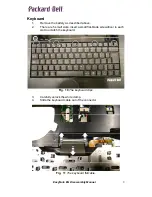
Page 9: ...y as described above 2 There are 5 small slots insert a small flat blade screwdriver in each slot to unlatch the keyboard Fig 10 The keyboard clips 3 Carefully unlock the white clamp 4 Slide the keybo...

Page 10: ...he CPU fan 3 Disconnect the fan s power cable 4 Take the fan out of the notebook Heatsink 1 Remove the battery and CPU fan as described above 2 Remove the 6 screws holding the heatsink 3 Carefully lif...

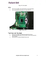
Page 11: ...tsink as described above 2 Use a small flatbed screwdriver to unlock the CPU Fig 14 The CPU Top Cover and Touchpad 1 Remove the battery and keyboard as described above 2 Remove the single screw of the...

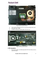
Page 12: ...rn over the unit and remove the 3 screws securing the top cover 5 Disconnect the 2 cables 6 Unclip the latches around the edge of the top cover Fig 16 The top cover screws LCD Assembly 1 Remove the ba...

Page 13: ...necting the LCD panel to the mainboard 3 Disconnect the cables from the WLAN card Make sure the tape securing them is removed everywhere 4 Remove the 6 hinge screws Fig 17 The hinge screws and LCD cab...

Page 14: ...EasyNote BG Disassembly Manual 14 Fig 18 The LCD cover screws 6 Lift of the bezel The LCD panel and webcam will be revealed 7 Remove the 4 screws Fig 19 The LCD panel screws 8 Take out the LCD panel...

Page 15: ...1 Remove the battery keyboard CPU fan and top cover as described above 2 Disconnect the VGA board connector cable from the mainboard 3 Remove the 2 screws Fig 20 The connectors and screw for VGA board...

Page 16: ...p cover as described above 2 Disconnect the cable connector 3 Remove the 2 screws holding the board Fig 22 The power Ethernet board 4 Remove the board Mainboard 5 Remove the battery keyboard CPU fan a...

Page 17: ...EasyNote BG Disassembly Manual 17 Fig 23 The mainboard screws and connectors 8 Remove the mainboard...

Page 18: ...ected by copyright No part of this guide may be photocopied or reproduced in any form or by any means without prior written consent from Packard Bell B V PACKARD BELL B V SHALL NOT BE LIABLE FOR TECHN...

Reviews: