background image

11

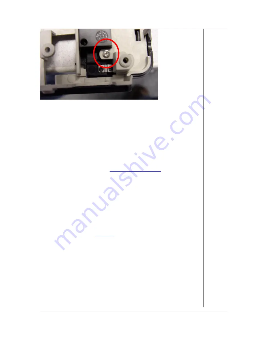
Picture 15. LCD Switch

LCD Screen Disassembly

LCD Lid Assembly

To remove the LCD lid assembly, perform the following steps:

1.  Remove the keyboard top cover as described above.
2.  Remove the LCD hinge covers; these are ‘

clicked’

 in place on the backside of the

notebook. The easiest way is to leverage them slightly using a flat-head
screwdriver.

3.  Disconnect the LCD cables.
4.  Disconnect the WLAN antenna. To do so, remove the CPU, the memory, and the

mini PCI cover as described in

WiFi LAN Adapter (Mini PCI)

. The antenna is

clicked onto the mini PCI card (see

Picture 4

).

5.  Note that the antenna might be secured on the main board or CPU fan using tape.

Remove the tape temporarily to release the antenna cable.

6.  Remove the 2*2 screws in the 2 LCD hinges.
7.  Gently lift the LCD screen assembly and ensure the WLAN antenna cable is free to

move as well.

LCD Bezel

To remove the LCD bezel, perform the following steps:

1.  Remove the 2 mylars near the hinges.
2.  Remove the 2 outer rubber stoppers, located on the top of the screen; the middle

rubber does not need to be removed.

3.  Remove the 4 screws (

Picture 16

).

4.  Remove the LCD bezel.

Summary of Contents for EasyNote B3

Page 1: ...Packard Bell EasyNote B3 Disassembly Manual ...

Page 2: ...Discharge 3 Power Supply Unit 3 System Disassembly 4 HDD 4 Memory Module 4 Optical Drive 4 CPU and Heat Sink Assembly 4 WiFi LAN Adapter Mini PCI 5 Keyboard 6 Speakers 7 LCD Screen Assembly 8 Main Board 8 Translation Board 10 Modem 10 Touchpad Assembly 10 LCD Switch 10 LCD Screen Disassembly 11 LCD Lid Assembly 11 LCD Bezel 11 Inverter Board 12 LCD Panel 12 Wireless Antenna 13 LCD Lid Hook 13 Noti...

Page 3: ... create a safety hazard Any indication of component replacement or printed wiring board modifications may void any warranty or exchange allowances Disassembly Instructions When disassembling the system unit follow these general rules n Turn off the power and disconnect the AC adapter and all cables and peripherals n Remove the battery Unlock both latches of the battery compartment and slide out th...

Page 4: ...ntil it is un installed in the computer Power Supply Unit Under no circumstances should you attempt to disassemble the power supply The power supply contains no user serviceable parts Inside the power supply are hazardous voltages that can cause serious personal injury Always return a defective power supply to your dealer WARNING Ensure that the computer is disconnected from its power source and f...

Page 5: ...de 3 Take out the memory module Optical Drive To remove the optical drive perform the following steps 1 Remove the optical drive bay cover 2 screws marked C on Picture 1 2 Carefully slide out the optical drive CPU and Heat Sink Assembly To remove the CPU and the CPU heat sink assembly perform the following steps 1 Remove bottom cover 5 screws marked B on Picture 1 2 Disconnect the power cable of t...

Page 6: ... LAN Adapter Mini PCI To remove the Wireless LAN Adapter mini PCI perform the following steps 1 Remove the bottom cover 5 screws marked B on Picture 1 2 Push the clips securing the card sideways the card will eject 3 Disconnect the WLAN antenna see Picture 4 4 Lift out the mini PCI card ...

Page 7: ...ard perform the following steps 1 Remove the 3 screws located in the battery compartment Picture 5 2 Push up the keyboard cover in the area indicated with the 2 arrows in Picture 5 3 Remove the 3 screws securing the keyboard shown in Picture 6 4 Gently lift out the keyboard 5 To disconnect the flat cable loosen the clip and slide out the cable Picture 7 Picture 5 Battery Compartment Picture 6 Keyb...

Page 8: ... Remove the keyboard cover as described in the chapter Keyboard 2 Disconnect the speaker cables as shown in Picture 8 Picture 9 and Picture 10 3 Remove the screws securing the speaker 2 screws per speaker 4 Lift out the speakers Picture 8 Speaker Cable Connector Picture 9 Left Speaker Connector ...

Page 9: ...AN antenna cable is free to move as well Main Board To remove the main board perform the following steps 1 Follow the steps described in the chapters HDD Optical Drive CPU and heat Sink Assembly Keyboard Speakers WiFi LAN Adapter Mini PCI and Memory Module Removing the entire LCD lid assembly is not required However you will need to disconnect the LCD cables 2 Remove all screws from the bottom bas...

Page 10: ...9 Picture 11 Bottom Base Screws Picture 12 Glide Pad Flat Cable Picture 13 Main Board Screws Under Keyboard Cover ...

Page 11: ...to the mini PCI slot 3 Disconnect the modem cable 4 Remove the 2 small screws of the modem board 5 Remove the modem board Touchpad Assembly To remove the touchpad assembly perform the following steps 1 Remove the top cover as described in steps 1 7 in chapter Main Board 2 Remove the 12 screws securing the metal shield to the top cover Note that 3 screws are covered with foil 3 Remove the metal shi...

Page 12: ...er as described in WiFi LAN Adapter Mini PCI The antenna is clicked onto the mini PCI card see Picture 4 5 Note that the antenna might be secured on the main board or CPU fan using tape Remove the tape temporarily to release the antenna cable 6 Remove the 2 2 screws in the 2 LCD hinges 7 Gently lift the LCD screen assembly and ensure the WLAN antenna cable is free to move as well LCD Bezel To remo...

Page 13: ...screw screw A in Picture 17 3 Take away the inverter board Picture 17 LCD Assembly Without Bezel LCD Panel To remove the LCD panel perform the following steps 1 Remove the 4 screws holding the hinges marked B in Picture 17 2 Remove 2 screws holding the LCD panel brackets indicated with C in Picture 17 you only need to remove the screws in the middle ...

Page 14: ...s Antenna To remove the wireless antenna perform the following steps 1 After removing the LCD panel remove the tape holding the antenna 2 Remove the screw see Picture 18 Picture 18 Wireless Antenna Screw LCD Lid Hook To remove the LCD lid hook perform the following steps 1 After removing the LCD panel you can take out the hook ...

Page 15: ... FURNISHING PERFORMANCE OR USE OF THIS MATERIAL Copyright 2005 NEC Computers International B V All rights reserved Packard Bell is a trademark of NEC Computers International B V The names of actual companies and products mentioned herein may be trademarks and or registered trademarks of their respective owners The software described in this guide is furnished under a license agreement or nondisclo...

Reviews: