background image


6

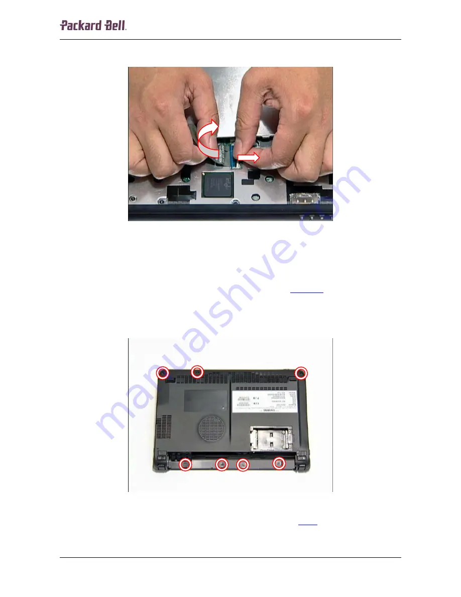
4.  Before removing the keyboard entirely, carefully release the white clip securing the flat 

cable and disconnect the cable from the header on the main board. 


Fig. 5 Releasing the keyboard flat cable. 


5.  Remove the keyboard entirely. 

Top and Base Cover 

To remove the top and base cover, first remove the keyboard (see 

Keyboard

 on page 5) and then 

perform the following steps: 
 

1.  Turn the notebook upside down. 
2.  Remove the four screws located in the battery compartment. 


Fig. 6 Removing the battery compartment and base cover screws. 


3.  Remove the other three screws securing the base cover (see 

Fig. 6

). 

4.  Turn the notebook over so the top is facing up. 

Packard Bell dot Disassembly Manual 

Summary of Contents for DOT S series

Page 1: ...Packard Bell dot Disassembly Manual...

Page 2: ...ostatic Discharge 3 Power Supply Unit 3 Battery 4 Keyboard 5 Top and Base Cover 6 USB LED Power Card Reader Board 9 LCD Assembly 10 LCD Bezel 13 Webcam 15 Microphone 16 LCD Panel 17 LCD Brackets and L...

Page 3: ...ny warranty or exchange allowances Disassembly When disassembling the system unit follow these general rules Turn OFF the power to the system and all peripherals using the power button Unplug the AC a...

Page 4: ...e notebook Power Supply Unit Under no circumstances should you attempt to disassemble the power supply The power supply contains no user serviceable parts Inside the power supply are hazardous voltage...

Page 5: ...e down Note Use an anti static mat or something soft like a piece of cloth underneath the notebook to prevent damage to the exterior of the notebook 4 Slide the battery lock unlock latch into the unlo...

Page 6: ...p is facing up and open the LCD completely 2 Release the keyboard by prying it up along the top side of the keyboard There are four tabs holding the keyboard in place on the front Fig 3 Releasing the...

Page 7: ...d Base Cover To remove the top and base cover first remove the keyboard see Keyboard on page 5 and then perform the following steps 1 Turn the notebook upside down 2 Remove the four screws located in...

Page 8: ...the touchpad flat cable from the header on the main board Fig 7 Disconnecting the touchpad cable 6 Remove the six screws securing the top cover Fig 8 Removing the top cover screws Packard Bell dot Dis...

Page 9: ...the LED panel Fig 9 Location of the LED panel notches 8 Turn the notebook over so the top is facing up 9 Pry loose the LED panel 10 Remove the two screws underneath the LED panel 11 Pull the top cover...

Page 10: ...Board To remove the USB LED power card reader board first remove the top cover see Top and Base Cover on page 6 and then do the following 1 Remove the three screws securing the USB LED power card rea...

Page 11: ...he header on the USB LED power card reader board and remove the board Fig 14 Disconnecting the USB LED power card reader board cable LCD Assembly To remove the LCD assembly first remove the USB LED po...

Page 12: ...oot pads 3 Remove the screws that became accessible after removing the footpads see Fig 15 4 Turn the notebook over so the top is facing up 5 Disconnect the LCD cable from the main board Fig 16 Discon...

Page 13: ...dapter Fig 17 Disconnecting the antenna cables Note The black antenna cable is connected to MAIN the white antenna cable to AUX 7 Clear the two antenna cables and remove them from the housing Fig 18 C...

Page 14: ...and remove it from the unit Fig 20 Removing the LCD assembly Note Ensure that all cables are clear of the base before lifting the LCD assembly upward LCD Bezel To remove the LCD bezel first remove th...

Page 15: ...essible after removing the covers Fig 21 Location of the LCD bezel screws 3 Starting from the inside edges carefully pry open the LCD bezel it has been clicked into place Fig 22 Releasing the LCD beze...

Page 16: ...g the LCD bezel Webcam To remove the webcam first remove the LCD bezel see LCD Bezel on page 13 and then do the following 1 Disconnect the cable from the header on the webcam module Fig 24 Location of...

Page 17: ...ule Microphone To remove the microphone first remove the LCD bezel see LCD Bezel on page 13 and then do the following 1 Disconnect the cable from the header on the microphone module Fig 26 Location of...

Page 18: ...hone module LCD Panel To remove the LCD panel first remove the microphone see Microphone on page 16 and then perform the following steps 1 Remove the five screws securing the LCD module Fig 28 Locatio...

Page 19: ...sides lift out the panel and remove it from the unit Fig 30 Removing the LCD panel LCD Brackets and LCD Cable To remove the LCD brackets and the LCD cable remove the LCD panel see LCD Panel on page 1...

Page 20: ...2 Remove any adhesive tape securing the LCD cable Fig 31 Clearing the LCD cable 3 Carefully disconnect the LCD cable from the header Fig 32 Disconnecting the LCD cable Packard Bell dot Disassembly Man...

Page 21: ...the other side of the LCD panel The brackets are paired diagonally observe the markings on the brackets Wireless LAN Adapter To remove the wireless LAN adapter first remove the top and base covers see...

Page 22: ...SB LED power card reader board see USB LED Power Card Reader Board on page 9 remove the wireless LAN adapter see Wireless LAN Adapter on page 20 and then perform the following steps 1 Disconnect the s...

Page 23: ...of the main board screw 3 Lift out the main board Fig 38 Removing the main board Speaker Assembly To remove the speaker assembly first remove the top cover see Top and Base Cover on page 6 and then pe...

Page 24: ...sive tape securing the speaker cables to the main board Fig 39 Clearing the speaker cables 2 Remove the four screws securing the speaker assembly to the top cover Fig 40 Location of the speaker assemb...

Page 25: ...mbly Hard Disk Drive To remove the hard disk drive first remove the main board see Main Board on page 21 and then perform the following steps 1 Remove the two screws securing the hard disk drive brack...

Page 26: ...down on the bracket to prevent damaging the main board 3 Remove the four screws Phillips head on the metal bracket holding the hard disk drive Fig 44 Location of the hard disk drive bracket screws No...

Page 27: ...acket Memory To remove the memory installed first remove the main board see Main Board on page 21 and then perform the following steps 1 Release the clip on each side securing the memory module the mo...

Page 28: ...remove the heat sink first remove the main board see Main Board on page 21 and then perform the following steps 1 Turn the main board upside down 2 Disconnect the fan cable from the header on the mai...

Page 29: ...28 3 Remove the three screws securing the heat sink in designated order Fig 49 Location of the heat sink screws 4 Remove the heat sink Fig 50 Removing the heat sink Packard Bell dot Disassembly Manual...

Page 30: ...L DAMAGES RESULTING FROM THE FURNISHING PERFORMANCE OR USE OF THIS MATERIAL Copyright 2008 Packard Bell B V All rights reserved Packard Bell is a trademark of Packard Bell B V The names of actual comp...

Reviews: