SECTION 3 INSTALLATION
55
3.2.7 OUTPUT VOLTAGE RANGE CONFIGURATION, MODELS 140-AMX, 160-AMX,
345-AMX, 360-AMX, 390-AMX, and 3120-AMX
This paragraph describes the configuration of the Output Voltage Range for the Models 140, 160, 345, 360,
390, and 3120-AMX Power Sources. These models can be configured for either 0-135 VAC
l-n
, 0-204 VAC
l-n
, 0-
273 VAC
l-n
, or 0-341 VAC
l-n
. The 0-204 VAC range is designated as the VR1.5 output form. The 0-273 VAC
range is defined to be the VR2.0 output form, and, finally, the 0-341 VAC range is defined to be the VR2.5
output form. A Magnetics Module (Assembly No. 134310) is required for the 204, 273 and 341 VAC output
forms.
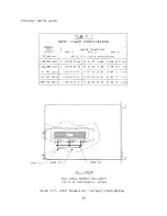
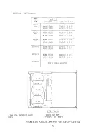
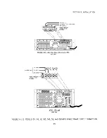
Refer to Figure 3.2.7 for location of components referenced below and range tap selection information.
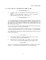
Conversion to the 204 VAC Output Range (VR1.5) is as follows:
1)
Remove the top cover of the Magnetics Module.
2)
Wire for 1.5:1 ratio as per wire table of Figure 3.2.7.
3)
Replace top cover of Magnetics Module.
4)
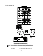
Connect Magnetics Module to the power source. The Magnetics Module is connected to the power
source by attaching P20 of the Magnetics Module to J20 of the power source. Also be sure to connect
the Chassis GND wire of the Magnetics Module to the CHS GND stud on the rear panel of the power
source.
5)
Set the Transformer Ratio Switch of the UPC to 1.5. (Refer to the
UPC-Series Operation Manual
for
details. This step does not apply to systems equipped with the UMC controller.) The Transformer
Ratio switch is set to 0.0 on systems not equipped with output transformers.
6)
Set the Amps to Volts Ratio Switch of the UPC to 15 for the Models 140-AMX, 160-AMX, 345-
AMX, and 360-AMX. Set the Amps to Volts Ratio Switch of the UPC to 30 for the Models 390-
AMX and 3120-AMX. (Refer to the
UPC-Series Operation Manual
for details. This step does not
apply to systems equipped with the UMC controller.)
7)
Calibrate the power source as stated in Section 6 of this manual.
Conversion to the 273 VAC Output Range (VR2.0) proceeds as above, except that the Magnetics Module is
wired for 2.0:1 ratio and Transformer Ratio Switch of the UPC is set for 2.0.
Likewise, conversion to the 341 V Output Range (VR2.5) proceeds as above, except that the Magnetics Module
is wired for 2.5:1 ratio and Transformer Ratio Switch of the UPC is set for 2.5.
The Transformer Ratio Switch of the UPC is set to 0.0 on systems without transformer-coupled outputs.
While the above procedure can be performed in the field, Pacific Power Source recommends that the system be
returned to the factory when transformer-coupled outputs are to be added to the system. This insures proper
connection and calibration of the entire system.
Summary of Contents for AMX series
Page 1: ......
Page 2: ......
Page 10: ......
Page 11: ......
Page 15: ......
Page 16: ......
Page 19: ...SECTION 2 SPECIFICATIONS 9B THIS PAGE INTENTIONALLY BLANK...
Page 21: ......
Page 22: ......
Page 23: ......
Page 25: ......
Page 26: ......
Page 27: ......
Page 28: ......
Page 29: ......
Page 30: ...SECTION 2 SPECIFICATIONS 19A FIGURE 2 1 2 E2 MODEL 160 AMX OUTPUT DERATING CURVES...
Page 31: ...SECTION 2 SPECIFICATIONS 19B THIS PAGE INTENTIONALLY BLANK...
Page 32: ......
Page 33: ......
Page 34: ......
Page 35: ......
Page 36: ......
Page 37: ......
Page 38: ......
Page 39: ......
Page 40: ......
Page 41: ......
Page 42: ......
Page 45: ...SECTION 2 SPECIFICATIONS 31B THIS PAGE INTENTIONALLY BLANK...
Page 46: ......
Page 47: ......
Page 48: ......
Page 49: ......
Page 50: ...SECTION 2 SPECIFICATIONS 36 FIGURE 2 2 3 OUTLINE DRAWING MODELS 125 140 160 345 360 AMX...
Page 51: ......
Page 56: ......
Page 57: ......
Page 58: ......
Page 59: ......
Page 60: ......
Page 61: ......
Page 62: ......
Page 63: ......
Page 64: ......
Page 65: ......
Page 66: ......
Page 67: ......
Page 70: ......
Page 71: ......
Page 72: ......
Page 73: ......
Page 74: ......
Page 75: ......
Page 76: ......
Page 77: ......
Page 80: ...SECTION 3 INSTALLATION 66 FIGURE 3 3 8 AMX SERIES INPUT WIRING DIAGRAM...
Page 82: ...SECTION 3 INSTALLATION 68 FIGURE 3 4 1 1 SINGLE PHASE OUTPUT CONNECTION...
Page 83: ......
Page 84: ......
Page 85: ......
Page 86: ...SECTION 3 INSTALLATION 72 FIGURE 3 4 2 1 SPLIT PHASE OUTPUT CONNECTION...
Page 87: ......
Page 88: ......
Page 89: ......
Page 90: ......
Page 91: ......
Page 92: ......
Page 93: ......
Page 94: ......
Page 95: ......
Page 96: ......
Page 97: ......
Page 99: ......
Page 100: ......
Page 101: ......
Page 102: ......
Page 104: ......
Page 105: ......
Page 106: ......
Page 107: ......
Page 108: ......
Page 109: ......
Page 110: ......
Page 112: ......
Page 114: ......
Page 116: ......
Page 117: ......
Page 118: ......
Page 120: ......
Page 121: ......
Page 122: ......
Page 124: ...SECTION 7 SERVICE 108B THIS PAGE INTENTIONALLY LEFT BLANK...
Page 125: ......
Page 126: ......
Page 127: ......
Page 128: ......
Page 129: ......
Page 130: ......
Page 131: ......
Page 132: ......
Page 133: ......
Page 134: ......
Page 135: ......
Page 136: ......
Page 137: ......
Page 138: ......
Page 139: ......
Page 140: ......
Page 141: ......
Page 142: ......
Page 143: ......
Page 144: ......
Page 145: ......
Page 146: ......
Page 147: ......
Page 149: ......
Page 150: ......
Page 151: ......
Page 152: ......
Page 159: ......


