33
INSTALLER
INFORMATION
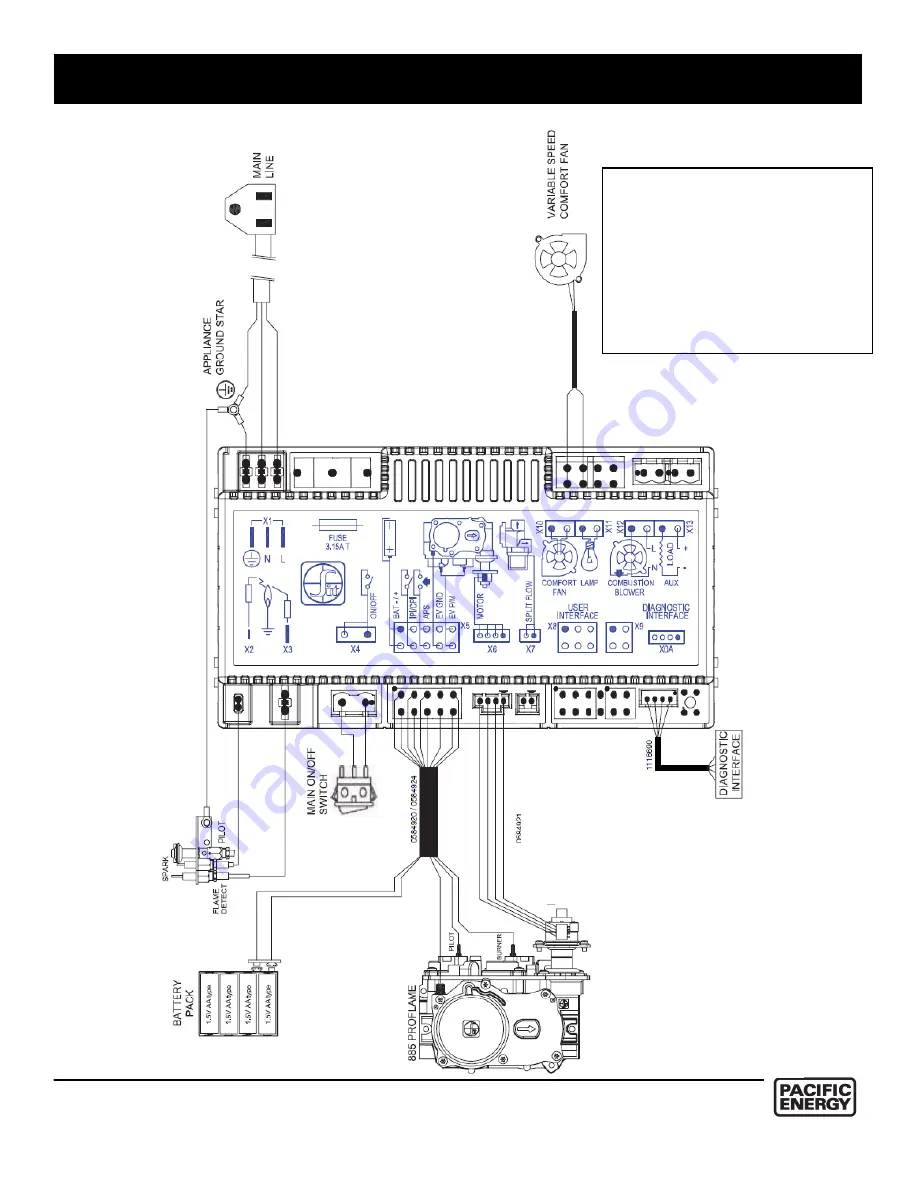
Caution:
Label all wires prior to
disconnection when servicing controls. Wiring errors can cause improper and dangerous operation.
Verify proper operation after servicing.
Wiring Diagram
Page 1: ...tely call your gas supplier from a neighbour s phone Follow the gas supplier s instructions If you cannot reach your gas supplier cal the fire department Installation and service must be performed by...
Page 2: ...rectly in line with the exhaust vent terminal for the horizontally vented gas fuelled heating appliance or equipment The sign shall read in print size no less than one half 1 2 inch in size GAS VENT D...
Page 3: ...Venting Components 21 Plumbing and Electrical 22 Gas Supply 23 Gas Pressure Check 23 Gas Pressure Testing Procedure 24 Pilot Adjustment 24 Propane Conversion 25 Door Installation Removal 26 Fan Insta...
Page 4: ...liance must be isolated from the gas supply piping system by closing its individual manual shut off valve during any pressure testing of the gas supply piping system at test pressures equal to or less...
Page 5: ...ing glass is provided with the appliance and shall be installed If the barrier becomes damaged the barrier shall be replaced with the manufacture s barrier for this appliance Any grill panel or door r...
Page 6: ...pay close attention to all Safety Warnings The manual contains important information on the unit s safe operation and maintenance When lit for the first time the fireplace will emit a slight odour fo...
Page 7: ...he gas valve and stepper motor Transmitter Remote Control with LCD Display The Proflame Transmitter uses a streamline design with a simple button layout and informative LCD display Fig 1 The transmitt...
Page 8: ...then press again the button SW1 to exit the synchronization phase The system is now initialized IFC Module The Proflame 2 Integrated Fireplace Control IFC board is a device that allows the automatic...
Page 9: ...ommand Turn off the Appliance With the system ON press the ON OFF Key on the Transmitter The Transmitter LCD display will only show the room temperature At the same time the IFC will be commanded to t...
Page 10: ...the transmitter will change to show that the room thermostat is ON and the set temperature is now displayed Fig 7 To adjust the set point press the up or down arrow keys until the desired set point t...
Page 11: ...Use the Up Down Arrow Keys Fig 1 to turn on off or adjust the fan speed fig 10 A single beep will confirm reception of the command Continuous Pilot Intermittent Pilot CPI IPI selection With the system...
Page 12: ...t etc When the IFC batteries are low a double beep will be emitted from the IFC board when it receives a command from the transmitter This is an alert for a low battery condition for the IFC board Whe...
Page 13: ...emblies for soot buildup If excessive buildup of soot is present have a qualified service person inspect and adjust unit for proper combustion Clean burners with a brush or vacuum cleaner paying close...
Page 14: ...14 OWNER S INFORMATION Lighting Instructions...
Page 15: ...15 INSTALLER INFORMATION Fireplace Dimensions ESTEEM ESTATE Figure 14 Estate Dimensions Figure 13 Esteem Dimensions...
Page 16: ...STEEM ESTATE ENCLOSED SIDE WALL 1 75 1 75 ENCLOSED BACK WALL NCR NCR ENCLOSED CEILING 4 4 ENCLOSED FRONT WALL NCR NCR EXPOSED SIDE WALL 8 8 VENT ENCLOSURE 1 1 EXTERIOR SOFFIT 30 30 NCR STANDS FOR NO C...
Page 17: ...is to be installed location of vent system and where gas supply piping may be plumbed Various installations are possible such as into an existing wall a corner a built in wall or a wall projection Du...
Page 18: ...and then pressing it into place Note Install screen insuring the step faces inward 3 Install the surround front by positioning it so as to clear the notches and secure by applying a downward pressure...
Page 19: ...justment from this chart Note The vent must not exceed a total length of 35 feet Any combination of rise and run may be used but must be constrained to the boundaries of this chart A Maximum of three...
Page 20: ...20 INSTALLER INFORMATION Figure 17 Venting This fireplace is certified for use with 4 x 6 5 8 coaxial venting components only It is permitted to only use certified venting for this appliance...
Page 21: ...components from different manufacturers is inadvisable Venting Components Figure 1 4 x6 5 8 Rigid Piping Cross Reference Chart Figure 21 4 x6 5 8 Rigid Piping Cross Reference Chart Figure 22 4 x6 5 8...
Page 22: ...ng that extends out of the unit as seen in Figure 21 Please see the gas supply section for requirements of the gas supply A gas shut off valve is located inside the fireplace and may be accessed by re...
Page 23: ...must be installed in the gas supply line going to the gas control valve to minimize the possibility of any loose scale or dirt within the gas supply line from entering the control valve Check local co...
Page 24: ...n the valve which can be seen in Figure 25 After locating test ports loosen the screws within the ports using a flat tip screwdriver 3 Attach pressure gauge to the test ports 4 Turn gas supply back on...
Page 25: ...rifice to ensure a proper seal when installed To replace the pilot orifice you will need to remove the pilot hood which is held in place by a spring First remove the spring and then remove the hood by...
Page 26: ...ccess panel to attach the fan to the unit as in Figure 29 5 Reconnect the gas supply and power and push the inner firebox back into the fireplace cavity Installation before fireplace installation 1 Re...
Page 27: ...box seen in Figure 33 Removal 1 Remove the baffle by removing screws securing the front edge of the baffle seen in Figure 33 After removing the two screws you can slide the baffle out of the fireplace...
Page 28: ...r Deflector Burner Tray Installation Removal Installation Place the burner tray in the fireplace and secure with 4 screws using a screwdriver as seen in figure 35 Removal Remove the 4 screws seen in f...
Page 29: ...ks in front of the front log to hide the burner as seen in Figure 42 Note Do Not Block Burner Ports with Embers Removal 1 Remove embers from fireplace 2 Lift the decorative log off of the front log an...
Page 30: ...ace and secure with 4 screws using a screwdriver as seen in figure 45 Removal Remove the 4 screws seen in figure 45 using a screwdriver and remove the burner tray Glass Installation To install the gla...
Page 31: ...would result in flames that cause soot See Page 19 for optimum restrictor position To adjust the damper loosen the two screws that hold the air deflector in place Slide the damper down to a position...
Page 32: ...orcelain Panel Set Coffee Bean GASC PNSPCBA Porcelain Panel Set Copper GASC PNSPCUA Burner Set required Log Burner Set GASC SBRNLOGA Glass Burner Set GASC SBRNGLA Optional Components Broadway Blower K...
Page 33: ...NSTALLER INFORMATION Caution Label all wires prior to disconnection when servicing controls Wiring errors can cause improper and dangerous operation Verify proper operation after servicing Wiring Diag...
Page 34: ...______ __________________________________________________________________________________________________ ______________________________________________________________________________________________...
Page 35: ...35 INSTALLER INFORMATION...
Page 36: ...Technical support 1 250 748 1184 Web site www pacificenergy net 2975 Allenby Rd Duncan BC V9l 6V8...