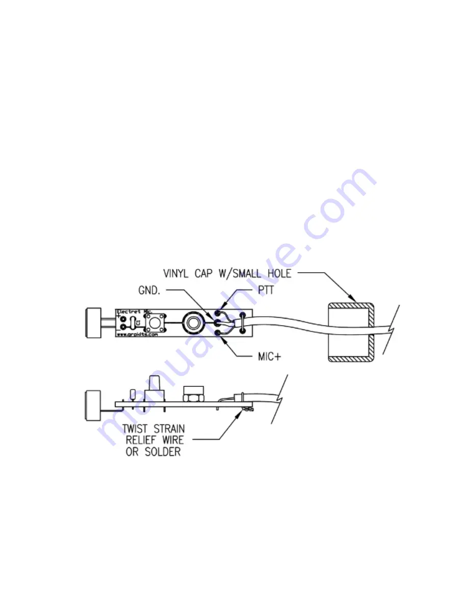
Prepare the vinyl cap by creating a hole in the center for the cable to pass through. This can be done with a punch,
or other tool or by melding carefully with a soldering iron tip. The hole needs to be approximately 1/8 inch for the
cable.
First, pass the cable end through the hole in the cap and prepare for connecting to the board by stripping the outer
jacket from approximately 1/2” of the cable.
Double check that the cable passes through the cap as shown in the drawing below
Strip and tin about 1/4” of each of the two leads and tin 1/4” of the bare braid.
Check with an ohmeter to see which of the two wires connect to which part of the 3.5mm plug. One wire will go to
each section, Tip or ring Ring and the bare braid connects to the shell or base.
You will need to wire correctly for your particular application so double check which part of the 3.5mm plug will
need to connect to the PTT and MIC before soldering to the board. The bare braid goes to the center (GND) pad.
Once soldered, use a section of resistor lead or similar bare wire to strain relief the cable.
Loop the wire through the holes as shown below, pull tightly and twist and/or solder to the board to secure the
cable. Use care not to overheat the wire as it will melt into the cable a bit during soldering.
Trim all component leads close to the bottom of the circuit board.
This completes the assembly of the microphone circuit board.
Wiring Check:
ElectretMic20180125
3


