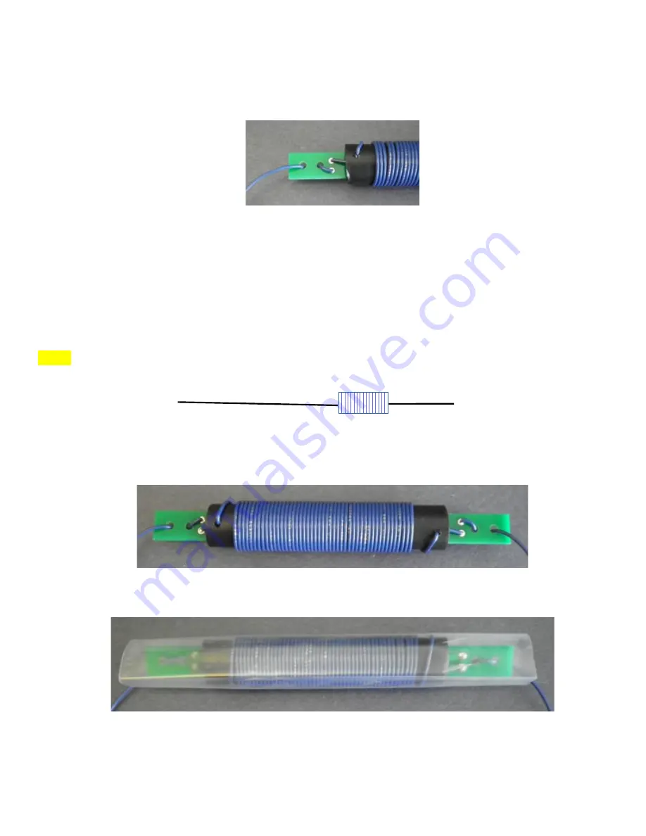
Insert the capacitor board into the coil form so that it is centered in the form, insert the stripped coil wire ends into
the board and solder the wires to the boards.
Repeat this process with the other coil to complete the trap set for the dipole.
Antenna sections
Each trap will be connected to the end of one 17 feet and one measuring 8 feet 3 inch wire by feeding the wire
through the outer hole, back through the next hole.
Strip approximately 1/4” of the insulation from the antenna wire, feed it through the solder pad hole and solder the
wire to the board.
Pull the end of the wire to remove any slack and to hold the wire in place in the board.
Repeat this process on the other end of the trap with the complementary wire and then do the same with the other
trap.
Each trap should now have the 17 ft wire attached to one end and an 8 ft 3 inch wire to the other to form each half
of the dipole.
Note:
The length includes everything up to the end of the coil so the actual wire may measure a bit shorter if
measured from the end of the trap board.
The 17’ sections will be the inner part of the antenna and the 8’ 3” ones will be the outer ends of the antenna.
Carefully slip a section of heat shrink tubing over each of the coil form.
If some turns of the coil become displaced or separated, use a small flat stick or tool to push them back in place
before shrinking the tubing.
2040DipoleV2_20180214
4
~17’
8’ 3”


