background image

Step 4

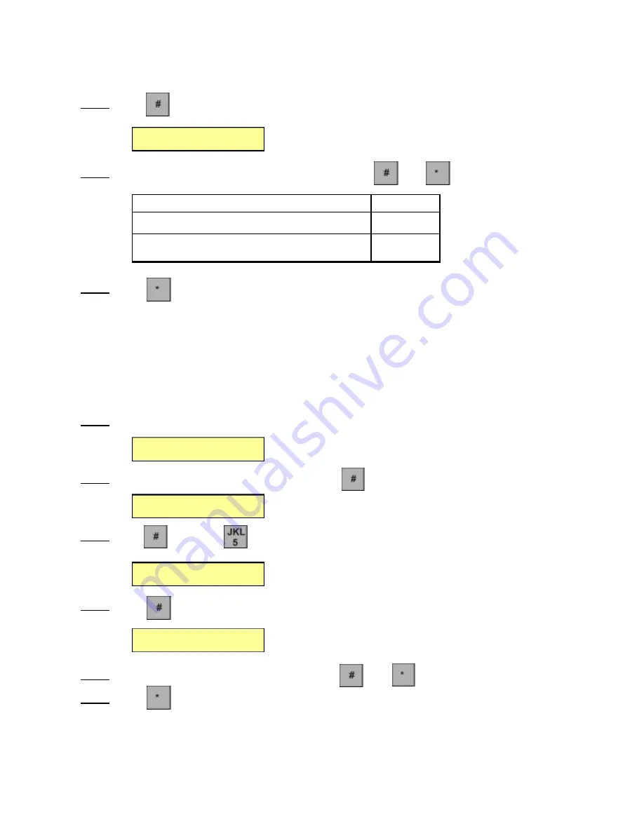
Press

the screen will show

Step 5

Enter the Back Light  Code from the table below then press

then

Step 6

Press

to exit from the programming mode or continue programming.

3.5 Facility Code

The Wiegand facility code is range from 001-255. The Wiegand facility code must be programmed if 

• If the AFGR9 is connected to the AeGIS 9000 Series Wiegand input or
• If the AFGR9 is connected to the AWCRM Wiegand input communicate via RS-485.

Facility Code is not necessary if the AFGR9 is configured as a standalone unit.

Step 1

Enter the Admin Code 

0000

, the the display will show:

Step 2

Enter the Magic Code (Password)

0000

, then press           the screen will show

Step 3

Press           then press            

three times

, the display will show

Step 4

Press            the screen will show  

Step 5

Enter the 3-digit Facility Code (001-255) then press

then

Step 6

Press

to exit from the programming mode or continue programming.

Back Light
3

_

MODE

CODE

If the keypad is pressed the LCD back light will be off

0

If the keypad is pressed the LCD back light will be on

in a few seconds. 

1

Password:_

ACS-BIO Setup
Set Parameter   1

Facility Code
4

019

Facility Code
4

_

Pach and Company

Page 12

07/28/04

AFGR9

Chapter 3. Set Parameters

Summary of Contents for AeGIS AFGR9

Page 1: ...AeGIS AFGR9 Installation and Programming Manual Pach Company 941 Calle Negocio Phone 1 888 678 7224 www pach co com San Clemente CA 92673 Fax 949 498 6879 July 28 2004...

Page 2: ...ity Code 12 3 6 Relay Select 13 3 7 Digital Input 13 3 8 Relay 1 Duration 14 3 9 Relay 2 Duration 15 3 10 ADMIN Code 16 3 11 MAGIC Code 16 Chapter 4 Enrollment 18 4 1 Primary Finger Print Enrollment 1...

Page 3: ...ions The products must be properly installed as specified maintained used as intended The serial number on the printed circuit board must match the serial number on the cabinet The system s failure is...

Page 4: ...andard Features 500 DPI Optical Finger Print Sensor 1000 Template Access Code capacity One 26 Bit wiegand Output Two RS 232 115200 Bps for database backup and firmware upgrade 2x16 character Liquid Cr...

Page 5: ...ith the system AFGR9 System XMFR 12VAC Power Transformer One 2 pins terminal connector inside the unit Two 12pins terminal connector inside the unit RS 232 cable Set of keys Part Number Description AS...

Page 6: ...is very essential Improper installation will void the warranty The AFGR9 can be installed as Wiegand Interface with the AeGIS 9000 Series Standalone unit or RS 485 using Figure 2 1 Printed Circuit Boa...

Page 7: ...0 WGN_D0 Wiegand output data 0 maximum distance 500 ft using18 gauge wire 11 GND System Ground Do not connect to earth ground 12 E_DATA External Data Not used 13 E_CLK External Clock Not Used 14 5V Ou...

Page 8: ...ceed 500 feet using 18 gauge wire There are four relays available if you use the Wiegand Interface Connection Two relays on AFGR9 see figure 2 3 and two relays on AeGIS 9000 Series See AeGIS 9000 Seri...

Page 9: ...2 2 Standalone Unit Connection The AFGR9 has two on board relay to control two doors at the same time See figure 2 3 Figure 2 3 STANDALONE Pach and Company Page 6 07 28 04 AFGR9 Chapter 2 Installation...

Page 10: ...must be used for this application The AWCRM has one built in relay to control door or gate You may also use the two built in relays on the AFGR9 to control another door or gate see figure 2 3 Figure...

Page 11: ...onnection The RS 232 is used for database backup The RS 232 DB9 is supplied See figure 2 5 for wiring diagram Figure 2 5 RS 232 Pin 20 Pin 23 Pin 24 BLACK WHITE GREEN Pach and Company Page 8 07 28 04...

Page 12: ...and date on the first line and Welcome to Pach and Company Access Control scrolling message on the second line Step 3 Adjust the LCD contrast see figure 2 1 to locate the LCD contrast adjustment Clock...

Page 13: ...press and the screen will show NOTE To keep the existing Date Display mode press Step 6 Press to exit from the programming mode or continue programming Password _ ACS BIO Setup Set Parameter 1 Date Di...

Page 14: ...to exit from the programming mode or continue programming 3 4 Back Light Step 1 Enter the Admin Code 0000 the the display will show Step 2 Enter the Magic Code Password 0000 then press the screen will...

Page 15: ...ured as a standalone unit Step 1 Enter the Admin Code 0000 the the display will show Step 2 Enter the Magic Code Password 0000 then press the screen will show Step 3 Press then press three times the d...

Page 16: ...ramming 3 7 Digital Input The REX input can be used for exit switch postal entry etc see diagram The REX input can be programmed to trigger relay 1 relay 2 or both Step 1 Enter the Admin Code 0000 the...

Page 17: ...for Digital Input Wiring Diagram REX Figure 3 5 1 REX Wring Diagram Step 6 Press to exit from the programming mode or continue programming 3 8 Relay 1 Duration Step 1 Enter the Admin Code 0000 the the...

Page 18: ...he the display will show Step 2 Enter the Magic Code Password 0000 then press the screen will show Step 3 Press then press seven times the display will show Step 4 Press the screen will show Step 5 En...

Page 19: ...ress and then Step 6 Press to exit from the programming mode or continue programming 3 11 MAGIC Code The MAGIC code is also called PASSWORD The default PASSWORD is 0000 You must change your PASSWORD c...

Page 20: ...ctory default The system will keep the finger print template but all names associated with the templates will be deleted 1 Turn off the system Unplug the transformer 2 Press and hold the then plugin t...

Page 21: ...er the 5 digit user ID then press the screen will show and the finger print scanner turn red means ready to scan your finger print The system will time out in 10 seconds if no finger print is detected...

Page 22: ...00 then press the screen will show Step 3 Press once and the screen will show Step 4 Then Press and the screen will show KEY CORRELATION KEY CORRELATION Space 1 P Q R S p q r s 7 A B C a b c 2 T U V t...

Page 23: ...ise press to exit from programming mode 4 3 Secondary Finger Print Enrollment The second finger print template is a backup template if the first finger print template cannot be recognized by the syste...

Page 24: ...7 Place your finger properly on top of the finger scanner do not use the same finger as a standard enrollment Step 8 Repeat Step 4 if you need to program another user s finger print otherwise press t...

Page 25: ...and ready to scan your finger print The system will time out in 10 seconds if no finger print is detected and the screen will show Step 6 Place your finger properly on top of the finger scanner the di...

Page 26: ...out in 10 seconds if no finger print is detected and the screen will show Step 7 Place your finger properly on top of the finger scanner the display will show Step 8 Enter the user name up to 15 chara...

Page 27: ...show Step 3 Press twice and the screen will show Step 4 Then Press and the screen will show Step 5 Enter a 5 digit user ID to be edited then press the screen will show Step 6 Press to replace the scre...

Page 28: ...ee times and the screen will show Step 4 Then Press and the screen will show Step 5 Press and the screen will show the next User Dir Step 6 Press twice to exit the programming mode NOTE Use for Page U...

Page 29: ...creen will show Step 5 Enter the 5 digit User ID the press the screen will show If is pressed the screen will return as shown on step 3 If is pressed the screen will show Step 6 If you want to delete...

Page 30: ...4 Then Press and the screen will show Step 5 If is pressed the screen will return as shown on step 3 If is pressed the screen will show then Step 6 Enter the Password 170845 then press then the scree...

Page 31: ...show Step 5 Press and the screen will show Step 6 Enter the current time in military time format HH the current hour in military format MM the minutes SS the second NOTE Press for backspace Then press...

Page 32: ...the system s database The RS 232 cable is included with the system see figure 2 5 for RS 232 wiring diagram 10 1 Installing the Software Step 1 Insert the CD ROM the display will show Step 2 Select ke...

Page 33: ...Step 3 Click the screen will show Step 4 Type your name and Company then Click the screen will show Pach and Company Page 30 07 28 04 AFGR9 Chapter 10 Install Software...

Page 34: ...Step 5 Click the screen will show Step 6 Click the screen will show Pach and Company Page 31 07 28 04 AFGR9 Chapter 10 Install Software...

Page 35: ...Step 7 Click the screen will show Step 7 Click and now you are ready to use the program Pach and Company Page 32 07 28 04 AFGR9 Chapter 10 Install Software...

Page 36: ...o open the AFGR9 software program the screen will show below Figure 11 1 Step 2 Select the COM port COM1 COM2 COM3 or COM4 Step 3 Click on File the screen will show Figure 11 2 Select COM PORT Pach an...

Page 37: ...ll show Figure 11 3 Step 5 Type the File name i e AFGR9 The Files of type is dbf Note You may change the folder name to save the database file The screen will show Figure 11 4 Pach and Company Page 33...

Page 38: ...cate user template will occur Pach and Company Page 34 07 28 04 AFGR9 Chapter 11 Backup the Database GET Template means receive the information from the system backup the system database Step 6 Click...

Page 39: ...the door gate will open 12 2 LCD Contrast The LCD contrast is preadjusted from the manufacturer You may need to adjust the contrast according to the location where you install the system See figure 2...

Reviews: