background image

 1

ThermoFlo Blower Assembly

(for PACE ThermoFlo power sources)

P/N 6008-0145-P1

Installation Instructions

Manual Number 5050-0431

Rev. A

For any questions regarding these instructions, contact the PACE Service
Department directly at:

Telephone (888) 535-PACE,  Fax (301) 483-7030

PACE Incorporated

9893 Brewers Court

Laurel MD 20723-1990

Summary of Contents for ThermoFlo 6008-0145-P1

Page 1: ...N 6008 0145 P1 Installation Instructions Manual Number 5050 0431 Rev A For any questions regarding these instructions contact the PACE Service Department directly at Telephone 888 535 PACE Fax 301 483...

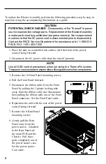
Page 2: ...nect the AC power cable from the unit if present NOTE Use all ESD control precautions when servicing the ThermoFlo system Thepowersourcecontainsassembliesutilizingstaticsensitivecomponents 3 Remove th...

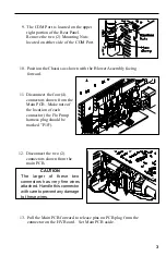
Page 3: ...4 connectors shown from the Main PCB Make note of the location of each connector the Flo Pump harness plug should be marked P10 13 Pull the Main PCB forward to release pins on PCB plug from the connec...

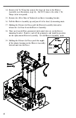
Page 4: ...of its four 4 mounting studs 17 Holding the Blower Air Hose pull the Blower Assembly forward to release the Air Hose from the Blower Assembly 18 There are four 4 Blue grommets with metal sleeves on t...

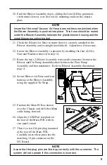
Page 5: ...x Nuts and Washers removed in step 14 23 Route the two 2 Blower Assembly wires with connector between the Blower and Flo Pump Assemblies then between the Flow Pump Assembly and the transformer Refer t...

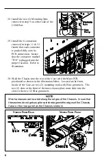
Page 6: ...Chassis into the rear of the Case with the Main PCB positioned as shown in the illustration below Located at the front inside of the Case are two 2 mounting studs with Blue grommets The two 2 slots a...

Page 7: ...ght to make changes to specifications contained herein at any time without notice Contact your local authorized PACE Distributor or PACE Incorporated to obtain the latest specifications The following...

Reviews: