


PACE Sodr-X-Tractor Handpiece
©2008 PACE Inc., Southern Pines, NC. All Rights Reserved
Page 6 of 11
www.paceworldwide.com
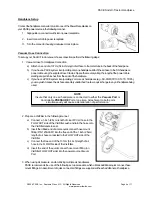
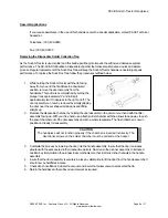
For maximum productivity and proper fit, install tips into your Sodr-X-Tractor when the heater is hot.
1. Insert the tip fully into the heater bore using the supplied tip tool (P/N 1100-0206).
2. Gently tighten the Heater Set Screw.
3. Recheck the Heater Set Screw periodically to insure that it remains snug.
Temperature Setting
To save tip life and reduce the possibility of damage to the PCB, PACE recommends using the lowest possible tip
temperature that will provide rapid yet controllable melt of the entire solder joint. Begin with an operating
temperature of 316°C (600°F) and adjust as necessary. Tip temperatures in excess of 399°C (750°F) may cause
damage. For safest removal, some components on extra heavy assemblies may require preheating or auxiliary
heating.
Burn In Procedure
The following Burn In procedure must be performed to insure optimum performance and life
of this product:
1.
Insure that system is located in a well-ventilated area on Initial power up.
2.
Remove plastic cap from end of Heater Assembly (If present).
3.
Connect Handpiece to PACE system Power Source.
4.
Set Handpiece Tip temperature to 316°C (600°F). Burn Handpiece in for 10 minutes at this
temperature.
5.
Set Handpiece Tip Temperature to 427°C (800°F). Heater Assembly will again emit smoke. Burn
Handpiece in at this temperature until emission of smoke ceases. Approximately 15 minutes.
6.
Operate Handpiece in a normal manner.
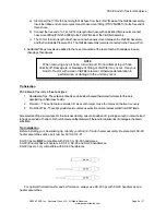
Tip Preparation
Proper tip preparation will insure optimum results and increase tip life. Follow this procedure before each component
removal or land preparation operation and prior to storage of the handpiece in its Tip & Tool Stand.
1. Ensure that the installed tip is at set tip temperature.
2. Using a moistened sponge, remove all solder dross and flux residue from the tip.
3. Using a large gauge, flux cored wire solder, tin the end of these tips. Proper tinning enhances heat
transfer to lands and extends tip life.
4. During Flo desoldering or Thru-hole desoldering, on heavily fluxed or contaminated boards, debris
may collect inside the tip bore. If this occurs, clean the tip bore with the Sodr-X-Tractor Tip Cleaning
Kit (PACE part number 6993-0200).
CAUTION
During tip installation, hold the handpiece with the heater pointed at an up
ward angle to prevent injury.
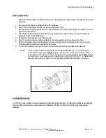
NOTE
Periodically, clean the heater bore with a properly sized 3/16" O.D. wire brush
(P/N 1127-0014-P5) to insure optimum heat transfer and proper tip grounding.


