GENERAL INFORMATION
PARTS IDENTIFICATION
TABLE 1.
MICRO BENCH TOP SYSTEMS (MBT-100/100E) PARTS IDENTIFICATION
•
VARIABLE TEMPERATURE CONTROL (Jl)-provides varrable temperature
c
onirol ror
EJr..
tractor Handpiece Tip temperau,re.
•
INDICATOR LIGHT-amber ngnt 1ratcates Main Power sw,tcn 1s -oN-.
•
MAIN POWER SWITCH-
c
ontrols input power within Micro Bench Top System.
•
PRESSURE CONTROL-air control ror hot-alr Jet mode.
•
VACUUM FITTING-vacuum tlow
re,
solder removal.
•
OUTPUT POWER RECEPTACLE 1J1)-connects power rrom Micro Bench Top System to
Extractor Handptece.
•
VISIFILTER
™
-collects and prevents foreign sustances rrom entering the Motor/Pump
Assembly.
•
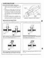
EXTRACTOR HANDPIECE-1001 used ror de.soldering, hot air pressure (blind side solder
removaQ and hot-air jet mode (removes solder connections and shrinks tubing)
fun
c
t ions.
{t--
•
VACUUM CONTROL SWITCH-Extra
c
tor Handpieca •ON/OFF" switch activa1e.s Moto(/Pump.
•
EXTR ACTOR TIP-heats and extracts solder lrom components.
•
HEATER ASSEMBLY -provides heat to Extraclor Handpiece Tip.
•
CUBBY HOLD
ER
-
conve
n
i
ently stores Extractor Handpiece.
•
EARTH GROUND TERMINAL-prcvides a
ground
between the M
i
cro
Bench Top Sys:em and
PCB, thus preventing
an
electrical charge rrom damaging sensitive components.
•
AC
POWER
RECEPTACLE -provides AC power to Mi
c
ro Bench Top System Imm AC outlet
through Power Cord.
•
VOLTAGE SELECTOR SWITCH-selects proper voltage which corresponds with input line
voltages. (NOTE: Switch must be placed in the proper position belore plugging in P'olver Cord).
•
POWER CORD-provides
main
power rrom AC outlet to AC Power R e
c
epta
c
le.
•
LINE FUSE (Ft)-provides overloaj protection for Micro Ben
c
h Top System.
•
CIRCUIT
BREAKER (CB1)-provic!es overload protection for Micro Bench Top System.
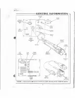
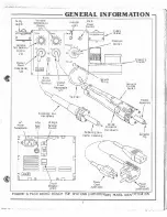
Figure 2 identifies the controls and indicators required lor operation on the Micro Ben
c
h Top
System(s) (MBT-100/lOOE) and the Extractor Handpiece. Refer to Table 1 and Figure 2 for location
and Identification of ea
c
h part.
4


