background image

COMPONENT VIDEO


Component video output 
for 

analog

 HDTV

AUDIO OUT


Audio outputs 
(stereo, R and L)

CABLE IN


From cable 
service-provider

VIDEO OUT


Composite 
video output

Power input 
(make this connection  
last of all)

OPTICAL AUDIO OUT


Optical S/PDIF  
audio output

ETHERNET


For future use

HDMI


Video and audio output 
for 

digital

 HDTV

USB (Universal Serial 
Bus) port


For future use

IR RECEIVE


Infra-red input from a 
remote “eye”

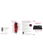
DC550DR High-definition digital set-top

HDTV with optional home theater

using a single video and audio connection

SDTV only

using composite video and audio connections

HDTV only

using separate video and audio connections

HDTV and home theater

using component video and digital audio connections

SDTV, VCR/DVD recorder, and home theater

using composite video and audio connections

SDTV and VCR/DVD recorder

using composite video and audio connections

Home Theater

HDTV

Cable

Input 

HDMI

HDMI

DC550DR

HDMI

IN

OUT

HDMI

HDMI

HDMI

LEFT

AUDIO IN

RIGHT

AUDIO IN

HDTV

Cable

Input 

HDMI

DC550DR

Pb

Y

Pr

COMPONENT 

VIDEO IN

Component video

L and R audio

- OR -

- AND -

HDMI

L and R audio

Component

video

HDMI

LEFT

AUDIO

IN

RIGHT

AUDIO

IN

DIGITAL 

OPTICAL

AUDIO IN

Pb

Y

Pr

HDTV

Cable

Input 

DC550DR

Component video

L and R audio

Home 

Theater

COMPONENT 

VIDEO IN

Pb

Y

Pr

COMPONENT 

VIDEO OUT

Pb

Y

Pr

COMPONENT 

VIDEO IN

- OR -

- AND -

Digital 

optical audio

Digital optical audio

Component video

Component video

L and R audio

LEFT

AUDIO IN

RIGHT

AUDIO IN

Cable

Input 

SDTV

DC550DR

Composite video

L and R audio

VIDEO IN

ANTENNA/RF

 IN

RF Connector

- OR -

- AND -

Composite video

L and R audio

RF cable

LEFT

AUDIO

IN

RIGHT

AUDIO

IN

SDTV

Cable

Input 

DC550DR

VCR/DVD

Recorder

Composite video

L and R audio

VIDEO

IN

LEFT

AUDIO

IN

RIGHT

AUDIO

IN

VIDEO

IN

LEFT

AUDIO

OUT

RIGHT

AUDIO

OUT

VIDEO

OUT

ANTENNA/RF

 IN

ANTENNA/RF

IN

TV/RF 

OUT

RF Connector

- OR -

- AND -

Composite video

Composite video

L and R audio

L and R audio

RF cable

RF cable

SDTV

Cable

Input 

DC550DR

VCR/DVD 

Recorder

Composite video

L and R audio

LEFT

AUDIO

IN

RIGHT

AUDIO

IN

LEFT

AUDIO

IN

RIGHT

AUDIO

IN

VIDEO

IN

VIDEO

IN

LEFT

AUDIO

OUT

RIGHT

AUDIO

OUT

VIDEO

OUT

LEFT

AUDIO

OUT

RIGHT

AUDIO

OUT

VIDEO

OUT

LEFT

AUDIO

IN

RIGHT

AUDIO

IN

VIDEO

IN

LEFT

AUDIO OUT

RIGHT

AUDIO OUT

VIDEO

OUT

LEFT

AUDIO IN

RIGHT

AUDIO IN

VIDEO

IN

CABLE / TV

VCR

Home Theater

ANTENNA/RF

 IN

TV/RF 

OUT

ANTENNA/RF

 IN

RF Connector

- OR -

- AND -

Composite video

L and R audio

RF cable

RF cable

Composite video

L and R

audio

POWER light


Lights green when your set-top is on; not lighted when your  
set-top is in standby or is disconnected from the power supply  

REMOTE light


Lights green when your set-top is receiving 
a signal from your remote control

HD light


Lights blue when your set-top outputs  
High-Definition Television (HDTV) content

DATA light


Lights yellow when your set-top is receiving 
data and when there is an unread message

TO TV

RF output to  
TV (or VCR)

Note:

 Video signals fed through a VCR or DVD recorder may be affected by copyright protection 

systems, which can cause distortion of the picture on your TV. If there is distortion when you 
view via the composite video path, the RF path may give a better picture.

E134-QSG-Iss1.indd   2

02/12/2013   12:17

Summary of Contents for DC550DR

Page 1: ...DC550DR Quick Start Guide High definition digital set top ...

Page 2: ...HDTV with optional home theater using a single video and audio connection Home Theater HDTV Cable Input HDMI HDMI DC550DR HDMI IN OUT HDMI HDMI HDMI ...

Page 3: ...N RIGHT AUDIO IN DIGITAL OPTICAL AUDIO IN Pb Y Pr HDTV Cable Input DC550DR Component video L and R audio Home Theater COMPONENT VIDEO IN Pb Y Pr COMPONENT VIDEO OUT Pb Y Pr COMPONENT VIDEO IN OR AND Digital optical audio Digital optical audio Component video Component video L and R audio ...

Page 4: ... using composite video and audio connections LEFT AUDIO IN RIGHT AUDIO IN Cable Input SDTV DC550DR Composite video L and R audio VIDEO IN ANTENNA RF IN RF Connector OR AND Composite video L and R audio RF cable ...

Page 5: ...DIO OUT RIGHT AUDIO OUT VIDEO OUT ANTENNA RF IN ANTENNA RF IN TV RF OUT RF Connector OR AND Composite video Composite video L and R audio L and R audio RF cable RF cable Note Video signals fed through a VCR or DVD recorder may be affected by copyright protection systems which can cause distortion of the picture on your TV If there is distortion when you view via the composite video path the RF pat...

Page 6: ...ly using separate video and audio connections LEFT AUDIO IN RIGHT AUDIO IN HDTV Cable Input HDMI DC550DR Pb Y Pr COMPONENT VIDEO IN Component video L and R audio OR AND HDMI L and R audio Component video HDMI ...

Page 7: ...Bus port For future use IR RECEIVE Infra red input from a remote eye DC550DR High definition digital set top POWER light Lights green when your set top is on not lighted when your set top is in standby or is disconnected from the power supply REMOTE light Lights green when your set top is receiving a signal from your remote control HD light Lights blue when your set top outputs High Definition Tel...

Page 8: ...IN RIGHT AUDIO IN VIDEO IN VIDEO IN LEFT AUDIO OUT RIGHT AUDIO OUT VIDEO OUT LEFT AUDIO OUT RIGHT AUDIO OUT VIDEO OUT LEFT AUDIO IN RIGHT AUDIO IN VIDEO IN LEFT AUDIO OUT RIGHT AUDIO OUT VIDEO OUT LEFT AUDIO IN RIGHT AUDIO IN VIDEO IN CABLE TV VCR Home Theater ANTENNA RF IN TV RF OUT ANTENNA RF IN RF Connector OR AND Composite video L and R audio RF cable RF cable Composite video L and R audio ...

Page 9: ... and other equipment Once you have decided which audio and video connections you need to make refer to the illustrations in this guide to connect your DC550DR to your TV and other A V equipment 4 Turn on your DC550DR Plug the 5 volt cord from the power supply unit into the power input socket labelled DC IN 5V on the rear panel of your DC550DR then plug the power supply unit into the wall AC outlet...

Page 10: ...ONENT VIDEO No HDMI adapter required or use an HDMI to DVI cable Alternate audio connections Audio quality Audio connections Top OPTICAL AUDIO OUT S PDIF High AUDIO OUT stereo L and R Note If you use the optional RF connections shown by dashed lines in the setups overleaf you must tune your TV and VCR to your set top s VHF output channel 3 or 4 consult your cable service provider to find which cha...

Page 11: ...e USER SETTINGS menu is displayed on your screen 3 Use the L R U and D buttons to navigate the menus and the OK Select button to confirm your choices See the example below 4 Press POWER to remove the menu and return to normal viewing OK Select OK Select OK Select OK Select TV Aspect Ratio 4 3 16 9 TV Aspect Ratio 4 3 16 9 PACE USER SETTINGS TV Aspect Ratio TV Display Capability Auto Pillarbox Clos...

Page 12: ...ubtitles and alerts on your TV screen On or Off and Configure Captions Front Panel Settings Set the brightness level of the front panel lights but not the POWER light Standby Brightness Low Std or High Viewing Brightness Low Std or High HDMI Settings Choose an Audio Output Mode and to enable or disable automatic detection of a newly connected HDTV when using an HDMI cable Audio Output Mode Auto L ...

Page 13: ...d other equipment are plugged in and turned on Check that you have selected the appropriate A V input on your TV If you are using the HDMI connection make sure it goes directly from your set top to your TV Try disconnecting and reconnecting the standard HDMI cable Make sure the set top s TV Display Capability settings are appropriate for your TV Press the HD ZOOM button until a picture appears Is ...

Page 14: ...as been dropped Additional safety information This set top has been manufactured and tested with your safety in mind However improper use can result in potential electric shock property damage or fire hazards To disconnect power from the set top always disconnect its 5V DC power supply unit from the wall AC outlet rather than disconnect the 5 volt cord from the set top Therefore you must install y...

Page 15: ...ed viewing uses only unless otherwise authorized by Rovi Corporation Reverse engineering or disassembly is prohibited Open Source Licenses The software contained in this product may be covered by certain components consisting of free software or open source software A list of these components and a copy of the relevant copyright notices and license term notices that are required by such licenses a...

Reviews: