background image

MTS Systems Operation Manual  

©2004 PACE Inc., Annapolis Junction, Maryland 

Page 6 of 11 

All Rights Reserved 


Handpieces 


MTS  systems  can  be  used  with  any  combination  of  TD-100  ThermoDrive  Soldering  Irons,  MT-100 
MiniTweezers,  PS-70,  PS-90,  SX-70,  SX-80,  TT-65,  TJ-70,  TJ-80  and  TP-65.    All  handpieces  are 
purchased  separately.    The  MTS  system’s  handpiece  ports  are  either  black  or  red.    Red  ports  can 
connect  to  the  TD-100  and  MT-100  ONLY.    The  Black  ports  can  be  connected  to  the  PS-70,  PS-90, 
SX-70,  SX-80,  TT-65,  TJ-70,  TJ-80  or  TP-65.    FIXED  HEATER  HANDPIECES  CANNOT  BE 
CONNECTED  TO  THE  RED  PORTS  AND  HEATER  CARTRIDGE  HANDPIECES  CANNOT  BE 
CONNECTED TO THE BLACK PORTS BECAUSDE THE CONNECTORS ARE NOT COMPATIBLE.   
 

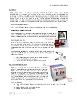
Handpiece Tip & Tool Stands 


The Tip & Tool Stand is usually placed on the workbench next to the power source.   


Adjusting the Angle of the Cubby  


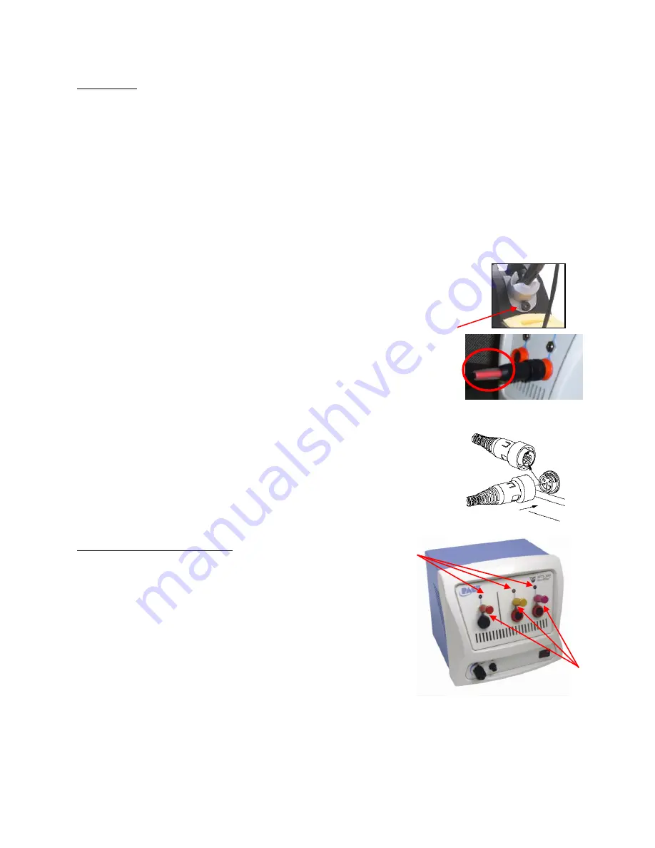
Some Handpiece Tip  & Tool stands have  adjustable  cubbies.  For example, the 
angle of the TD-100 Cubby may be adjusted by loosening the angle thumb screw 
slightly, adjusting the cubby to the desired angle, and tightening the thumb screw.   
 

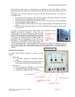
Handpiece Connection 


When  connecting  a  handpiece,  always  match  the  color  on  the  connector 
and handpiece port on the system.  For example, HC handpieces have the 
red  connector  and  will  only  connect  to  red  ports.    Likewise,  Fixed  Heater 
handpieces  have  black  connectors  and  can  only  be  connected  to  black 
ports. 
 
To  connect  the  handpiece  to  the  power  supply,  refer  to  the  figure  to  the 
right.  Connect the handpiece connector plug into the Power Receptacle in 
the following manner. 


1.  Align guide on the connector with slot on power receptacle. 
2.  Insert connector into power receptacle. 
3.  Turn the connector housing clockwise to lock in place. 


Operation of the MTS Systems 


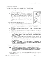
MTS  systems  require  the  use  of  Power  Modules.    The  Power 
Module selects the desired heat/performance level for operation.  
MTS  systems  come  standard  with  two  or  three  #7  Power 
Modules.  Additional Power Modules are available in performance 
levels  of  5,  5.5,  6,  6.5,  7.5,  8,  and  8.5.    Please  refer  to  the 
Accessory Section for Power Module part numbers.  A heat level 
of 5 corresponds to a nominal temperature of 500 

F; a heat level 

of  6.5  corresponds  to  a  nominal  temperature  of  650 

F,  etc.  

Actual temperatures may vary slightly due to tip geometry.   
 
Verify the following: 

a)  Power  cord  connection  between  an  appropriate  AC  supply  receptacle  and  the  power 

source. 

b)  Handpiece connection to the power source. 
c)  Desired Power Module is installed. 

Power 
Module 
Ports 

LED 
Indicators 

Thumb Screw 

Summary of Contents for 8007-0412

Page 1: ...VAC 8007 0414 MTS 200 SC System 230 VAC 8007 0415 MTS 200 SA System 115 VAC 8007 0412 MTS 200 SA System 230 VAC 8007 0413 MTS 300 System 115 VAC 8007 0418 B MTS 300 System 230 VAC 8007 0419 B MTS 350...

Page 2: ...n 4 Safety 5 System Set Up 5 Mounting Options 5 System Power Up 5 Handpieces 6 Handpiece Tip Tool Stands 6 Adjusting the Angle of the Cubby 6 Handpiece Connection 6 Operation of MTS Systems 6 Vacuum P...

Page 3: ...e FH channel the MTS 350 features 1 HC channel and 2 FH channels The system also comes standard with Auto Setback and Auto Off functions to preserve tip life Applicable Regulations MTS systems are ava...

Page 4: ...1 3 Amp 115 VAC 60 Hz Max OR 7 Amp 230 VAC 50 Hz Max Fuse 2 Amp SloBlo 115 V System 1 Amp TimeBlo 230 V System MTS 350 1 3 Amp 115 VAC 60 Hz Max OR 7 Amp 230 VAC 50 Hz Max Fuse 2 Amp SloBlo 115 V Syst...

Page 5: ...CE systems in a well ventilated area A fume extraction system such as those available from PACE are highly recommended to help protect personnel from solder flux fumes 6 Exercise proper precautions wh...

Page 6: ...ector and handpiece port on the system For example HC handpieces have the red connector and will only connect to red ports Likewise Fixed Heater handpieces have black connectors and can only be connec...

Page 7: ...Features These are pre programmed for 30 minute Auto Setback and 30 minute Auto Off which can be turned off by the switch on the back of the unit If the handpiece channel has not been used for 30 min...

Page 8: ...iFilter FLOW OUT side into the power source Vacuum Port 3 When using air pressure and or utilizing multiple air handpieces PACE recommends the use of the following set up procedure which utilizes addi...

Page 9: ...one of the same rated value Handpiece will not heat Defective Heater Change Tip Cartridge Power Source Malfunction Contact PACE Power Source Corrective Maintenance Packing Contents Description MTS 200...

Page 10: ...WARRANTY OF MERCHANTABILITY OR FITNESS FOR A PARTICULAR PURPOSE Seller will at its option repair or replace any defective products at its facility or other location approved by it at no charge to user...

Page 11: ...BRITE AUTO OFF and TEKLINK The following are registered trademarks and or service marks of PACE Incorporated Annapolis Junction Maryland U S A ARM EVAC FLO D SODR MINIWAVE PACE SENSATEMP SNAP VAC SOD...

Reviews:

Related manuals for 8007-0412