background image

22

BRAKE SERVICE

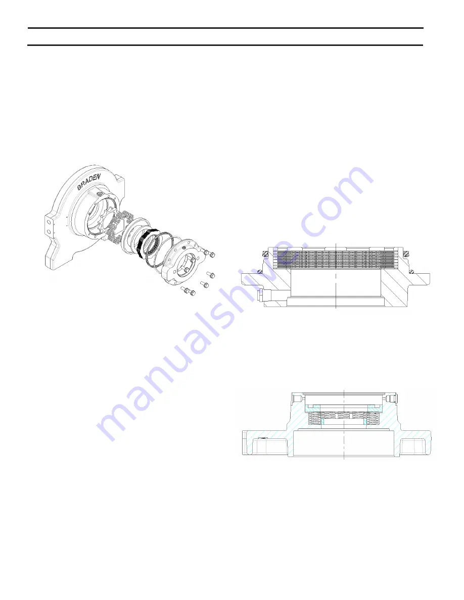
Disassembly

1.  Remove motor support by progressively loosening 

eight capscrews, relieving the brake pack’s spring load. 

Spring load will be relieved before capscrews disengage 

motor support. Remove O-ring, U-cup seal, brake pack 

(friction and steel discs), spacer and pressure plates, 

brake springs, and spring spacer.


Inspection

1.  Inspect sealing surfaces of motor support and brake cyl-

inder for wear and dings. Make sure the brake release 

port is open and free of contamination.

2.  Measure friction disc thickness with a caliper. Minimum 

reusable thickness is .055 inch (1.40 mm). Measure flat

-

ness of both friction and steel discs. These should be 

flat within .005 inch (0.13 mm). Look for signs of over

-

heating. Replace steel discs that show heat discoloring. 

Examine friction facing for missing material, cracks, or 

other damage. Replace as necessary. Inspect friction 

splines for wear and replace if worn to a point.

3.  Check spring free length with a caliper. Minimum length 

is 0.938 inch (23.8 mm). Inspect springs for bending 

or other damage. If any spring is suspect, replace all 

springs as a set. Mixing old and new springs can cause 

uneven pressure which contributes to poor brake ap-

plication, uneven friction disc wear, and possible spring 

failure.

Reassembly

1.  Begin reassembly by placing the motor support face-

down on a workbench. 

2.  Lubricate the new O-ring with oil and install onto the mo-

tor support. Lubricate the new U-cup seal and install so 

that the O-ring side of the seal is facing the winch motor. 

This allows the seal to expand when pressurized.

3.  Soak friction discs in oil. This will keep the discs from 

sticking together after spring pressure is applied.

4.  Insert a steel disc into the bore of the motor support, fol-

lowed by a friction disc. Alternate steel and friction discs 

until all are installed. The stack should finish with a steel 

disc on top.

5.  Place the brake housing end plate on a bench with cyl-

inder bore facing upward.

6.  Install the spring spacer, followed by the brake springs, 

pressure and spacer plates.

Summary of Contents for Braden TR20A

Page 1: ...ACCAR Inc All rights reserved LIT2736 February 2019 Printed in USA Visit our Website at www paccarwinch com for the most comprehensive collection of winch hoist and drive information on the Internet M...

Page 2: ...ll waste The U S Environmental Protection Agency has developed required practices called management standards for busi nesses that handle used oil and metal wastes Specific guidelines are available at...

Page 3: ...r 3 Find item number on parts list Show part number description and quantity required on your order 4 Refer to Parts List and show price for each component or assembly T Towing trailer application R R...

Page 4: ...ertain combinations of drum gear ratio motor and hydraulic flow may reduce or increase this rating D d Ratio The ratio of cable drum barrel diameter D to wire synthetic rope diameter d Current SAE sta...

Page 5: ...times 16 Use correct cable anchor for wire synthetic rope and pocket in drum 17 Do not use knots to secure or attach wire synthetic rope 18 The BRADEN designed wire synthetic rope anchors are not int...

Page 6: ...ial or unsafe practices which COULD result in personal injury and product or property damage if proper procedures are not followed WARNING This emblem is used to warn against hazards and unsafe practi...

Page 7: ...he static brake consists of three basic components 1 Spring applied multiple friction disk brake pack 2 Solid brake coupling 3 Hydraulic brake cylinder and spring plate The brake pack consists of alte...

Page 8: ...release at a pressure lower than required to open the counterbalance cartridge The extent to which the cartridge opens will determine the amount of oil that can flow through it and the speed at which...

Page 9: ...to move the clutch shift handle with a load on the cable Do not use cheaters to extend the shift handle length or other means to apply undue force on the shift handle A partially engaged drum clutch...

Page 10: ...perature conditions The use of oil having a high viscosity index will minimize cold start trouble and reduce the length of warm up periods A high viscosity index will minimize changes in viscosity wit...

Page 11: ...00 operating hours or three months whichever occurs first Use sight glass to check oil level The level should be within the upper and lower limits of the glass If additional oil is needed refer to the...

Page 12: ...icularly un der low ambient temperature conditions may result in temporary brake slippage due to high back pressures attempting to release the brake which could result in property damage severe person...

Page 13: ...ompounds EP 150 PREVAILING AMBIENT TEMPERATURE oF 40 30 20 10 0 10 20 30 40 50 60 70 80 90 100 110 120 130 oF oC 40 30 20 10 0 10 20 30 40 50 oC SHADED TEMPERATURE RANGE IN THE CHART ABOVE NOT RECOMME...

Page 14: ...a plugged or loose pilot orifice The pilot orifice is a small pipe plug with a hole drilled through it located behind the pilot port fitting on the brake valve If it becomes plugged it will prevent t...

Page 15: ...of Trouble A3 Improper planetary gear oil may cause the brake discs to slip Drain old gear oil and flush winch with solvent Thorough ly drain solvent and refill winch with rec ommended planetary gear...

Page 16: ...uces motor performance 4 Winch line pull rating is based on first layer of wire synthetic rope 5 Rigging and sheaves not operating efficiently TROUBLE PROBABLE CAUSE REMEDY E Winch runs hot Same as re...

Page 17: ...ing rope of the proper wind or lay When the load is slacked off the several wraps on the drum will stay closer together and maintain an even layer If rope of im proper lay is used the coils will sprea...

Page 18: ...18 TR20A CROSS SECTION Part number 09512 ADDITIONAL REFERENCE PUBLICATION For cross section diagrams and complete list of components please refer to LIT2732 Parts List for TR20A recovery winches...

Page 19: ...t 111420 1 015 Cover housing 111414 1 016 Washer 100858 16 017 Capscrew 11766 16 018 Plug 25665 2 TR20A COMPONENTS Part number 09512 ITEM NO DESCRIPTION PART NO QTY 019 16574 0012 Sight gauge 70193 1...

Page 20: ...ort by remov ing two bolts and two washers Remove brake coupling 4 Remove the free spool clutch assembly 5 Remove the gear housing cover by removing eight screws and eight washers Remove O ring 6 Remo...

Page 21: ...ve tie plates by removing eight screws and eight washers 8 Separate drum supports from drum 9 Separate gear housing from drum support by removing eight screws and eight washers 10 Remove seal and bear...

Page 22: ...t 3 Check spring free length with a caliper Minimum length is 0 938 inch 23 8 mm Inspect springs for bending or other damage If any spring is suspect replace all springs as a set Mixing old and new sp...

Page 23: ...d screws finger tight Next equally tighten the screws in a crisscross pattern com pressing the brake springs evenly Final tighten screws per torque chart Testing Brake Seals 1 Connect a hand pump with...

Page 24: ...th should be free of abnormal wear and pitting Al ways replace roll pins and shaft bushings with new WINCH ASSEMBLY Reassemble the winch in reverse order of the steps described in Winch Disassembly se...

Page 25: ...d high nuts Higher or lower torques for special applications will be specified such as the use of spanner nuts nuts on shaft ends jam nuts and where distortion of parts or gaskets is critical Lubricat...

Page 26: ...26 THIS PAGE INTENTIONALLY LEFT BLANK...

Page 27: ...g 60o F pounds sq in PSI X 6 895 kilopascals kPa kilopascals kPa X 0 145 pounds sq in PSI pounds sq in PSI X 0 0703 kilograms sq cm kg cm2 kilograms sq cm kg cm2 X 14 22 pounds sq in PSI pounds sq in...

Page 28: ...28 2019 PACCAR Inc All rights reserved LIT2736 February 2019 Printed in USA...

Reviews: