Pacbrake C44059 Installation Manual Download Page 5

INSTALLATION MANUAL - INSERT TITLE HERE, L1234 

PG 4 

INSTALLATION MANUAL - C44059 / C44061 / C44063 / C44065, L5855

PG  4

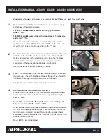
C44063 & C44065 KITS ONLY:


Under the hood, beside the fuel filter, locate the factory 3 pin 


Weather- Pac connector on the driver side of the engine (

shown  


by the arrow

). Remove the protective cap and install the mating    


connector in the Pacbrake harness. Install the removed protective   


cap on the unused connector on the Pacbrake harness - unless  


you have a performance module connected to it. If so, it connects  


to the Pacbrake connector.


NOTE:

 Some 1999 model year trucks and all 1998½ will require  


the use of a 3 pin triangular jumper harness to connect to the data  


link connector. See schematic pertaining to your kit #, found on page  


9-11. Proceed to Step 10.
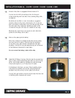
9


C44061 KIT ONLY:


Locate the diagnostic connector under the dash on the drivers side.  


Connect the male plug of the Pacbrake harness to the factory  


diagnostic connector. Secure the Pacbrake connector to the  


diagnostic connector using the supplied tie straps.
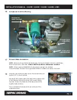
10


C44061, C44063 & C44065


Remove the air filter housing to access the passenger side firewall  


and locate the PCM (

shown in fig 10A

). Remove the C2 and C3  


connectors. Remove the plastic cover to access the wires. Pull back  


the conduit to give access for attaching wires into the factory harness.  


Use fig 10B as a guide to the pin locations. 

C2 CONNECTIONS

Locate the orange/black wire in pin 11 of the C2 connector. Cut this 

wire. Attach the brown wire of the Pacbrake harness to the PCM side. 

Attach the orange wire to the harness side of the orange/black wire. 

These connections are done using the supplied red heat shrinkable 

butt connectors.
Locate the brown wire in pin 21 of the C2 connector. Cut this wire and 

splice the blue wire of the Pacbrake harness into it using the supplied 

red heat shrinkable butt connectors.

C3 CONNECTIONS

Locate the orange/white wire in pin 13 of the C3 connector. Cut this 

wire and splice the yellow wire of the Pacbrake harness into it using 

the supplied red heat shrinkable butt connectors.
Using the heat gun, heat the connectors to provide a water tight seal 

on all heat shrinkable butt connectors. See the wiring diagram  

pertaining to your kit #, found on page 9-11.

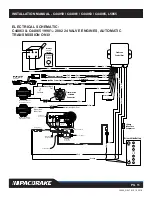
PCM AND TRANSMISSION CONNECTIONS

8

9

10 

A

10 

B

C1

C2

C3

C1

C2

C3

22

12

1

32

21

11

Powertrain Control

Module C2 (Diesel)

22

12

1

32

21

11

Powertrain Control

Module C3 (Diesel)

POWERTRAIN

MODULE C2

(DIESEL)

POWERTRAIN

MODULE C3

(DIESEL)

Summary of Contents for C44059

Page 1: ...C44059 C44061 C44063 C44065 PRXB EXHAUST BRAKE HIGH PERFORMANCE APPLICATION 1994 2002 DODGE RAM AUTOMATIC TRUCKS EQUIPPED WITH 47RE TRANSMISSIONS WITH 5 9L 24 VALVE CUMMINS DIESEL ENGINES ...

Page 2: ...ith an automatic 47RH transmission Heavy duty exhaust valve springs ARE MANDATORY for all 12 valve engines Pacbrake C14010 Spring Kit is included in the C44059 Kit Failure to install the heavy duty springs WILL result in engine damage Pacbrake C44061 Kit is a high performance PRXB exhaust brake designed to provide maximum retarding throughout the RPM range of your 1996 1998 Dodge 12 valve Cummins ...

Page 3: ... the harness to the Pacbrake control unit Secure the harness with the provided tie straps 3 Locate the plastic plate in the drivers side of the firewall Drill a hole large enough to feed the Pacbrake harness through Then feed the harness into the engine compartment from the cab side Apply silicon sealant around the loom to provide a seal 4 ON OFF SWITCH INSTALLATION ALL KITS Provided on the last p...

Page 4: ...p 8 7 THROTTLE SWITCH INSTALLATION C44059 C44061 KITS ONLY Locate the stud shown in the photo and remove the nut Install the switch assembly with the switch arm horizontal Re install the stud nut and tighten making sure the switch arm is behind the accelerator lever Adjust the switch by loosening the screws and positioning it to click just as the throttle returns to its released position Cycle the...

Page 5: ...e the PCM shown in fig 10A Remove the C2 and C3 connectors Remove the plastic cover to access the wires Pull back the conduit to give access for attaching wires into the factory harness Use fig 10B as a guide to the pin locations C2 CONNECTIONS Locate the orange black wire in pin 11 of the C2 connector Cut this wire Attach the brown wire of the Pacbrake harness to the PCM side Attach the orange wi...

Page 6: ...re to the harness side of the orange black wire These connections are done using the supplied red heat shrinkable butt connectors Locate the brown wire in pin 55 Cut this wire and splice the blue wire of the Pacbrake harness into it using the supplied red heat shrinkable butt connectors Locate the orange white wire in pin 10 Cut this wire and splice the yellow wire of the Pacbrake harness into it ...

Page 7: ...s 14 Remove the passenger side battery Place the compressor and bracket assembly into the battery box as shown in the photo Place and secure the battery on top of the compressor bracket Reinstall the hold down assembly Connect the corresponding weather pac connectors of the Pacbrake harness to the compressor Do not connect the battery cables at this time 15 Install the 90 fitting in the top of the...

Page 8: ...lbow Follow L5669 Installation Addendum included NOTE 12 Valve engines REQUIRE H D exhaust valve springs to be installed Contact Pacbrake Customer Service 800 663 0096 for installation procedure if required 18 Using the nylon airline provided connect the solenoid valve port marked CYL to the air cylinder Reconnect both positive battery terminals with the positive lead of the Pacbrake harness Recon...

Page 9: ...rence between the two pro grams is that the 48RE transmission will allow exhaust braking in 2nd and 1st gears where the factory 47RH RE transmission will not Test drive the vehicle If lock up will not hold during exhaust braking in 2nd or 1st gear re connect the orange wire LED SWITCH OPERATION RED Brake enabled and ready for activation GREEN Parameters are achieved and the Pacbrake controller is ...

Page 10: ... Unit Brown Brown Orange Pin Blue Brown Pin 4 5 Pin 6 Pin Pin 15 Pi n 16 Pin 1 9 Black White Black Pin 24 22 1 2 7 8 3 6 4 5 Orange Black Orange White Orange White Yellow Red Grey k c a l B Red 3 Amp Fuse Yellow Orange Pin 9 Pin 1 0 Orange Ignition Power Source PIN 54 PIN 55 PIN 10 Oran ge O BD I Plug 41 21 1 60 40 20 POWERTRAIN CONTROL MODULE Throttle Switch Pacbrake Switch Pin 1 Black Pin 2 Whit...

Page 11: ... A B Orange Pin 13 Black Grey Red Red Pin 23 Pin 18 Pacbrake Control Unit Brown Blue Brown Orange Pin Pin 4 5 Pin 6 Powertrain Control OBD IIPlug Module C2 Diesel Pin Pin 15 P in 1 6 Pin 19 Black White Blac k n i P 24 22 1 2 7 8 3 6 4 5 Orange Black Orange with White Wire Pin 15 Pin 7 Red Grey k c a l B Red Powertrain Control Module C3 Diesel 3 Amp Fuse Green Yellow Pin 8 Pin 7 Orange Ignition Pow...

Page 12: ... 5 Orange Black Brown for 98 99 Model Year Trucks Red Grey k c a l B Red 3 Amp Fuse Pin B Pin A Green Yellow Pin11 Pin12 Orange Diagnostic Connector Ignition Power Source Pin 7 Powertrain Control Module C2 Diesel Powertrain Control Module C3 Diesel 22 12 1 32 21 11 22 12 1 32 21 11 Connector Connector Pin 13 Orange with White Tracer Orange with White Tracer Pin 4 Blue Yellow Pin 15 Pacbrake Switch...

Page 13: ...RAM DASH SWITCH TEMPLATE MODEL YEARS 1994 1998 For C44072 and C44074 kits NOT using a shifter switch 1 4 Drill For C44073 C44075 and C44076 kits Flush with center of screw hole 1 4 Drill For C44059 C44061 C44063 and C44065 kits Flush with edge of panel Hood release handle cut out Cut out template along outer edge and align as shown DASH SWITCH TEMPLATE 1994 1998 ...

Page 14: ...ttom of dash bezel Cigarette Lighter Alternate Location At Bottom Of Page 1 4 Drill For C44073 C44075 and C44076 kits For C44072 and C44074 kits NOT using a shifter switch or 1 4 Drill Cut out template along outer edge and align as shown NOTE Template location is only a suggestion Access to back of this location is difficult and wires must be installed on switch terminals prior to installation DAS...

Reviews: