background image

Content 


Introduction - Description of operation - Important - Warranty....
Battery/Power monitor - Test program - Error Code......................
MCB functions................................................................................
Electronics terminals...................................................................
Hydro 1-3 Valve - Wiring diagram.................................................
Valves and Radio equipment........................................................
Hydro P/T - Wiring diagram..........................................................
Hydraulic valves - Service/Maintenance.......................................
Drawings..................................................................................
Trailer connectors.........................................................................
Control Unit and Produkt-Id.........................................................

6

www.p-light.com

established 2000

Introduction

Introduction

Thank you for choosing P-LIGHT from InnoNet AB. We hope that 

P-LIGHT facilitates and streamlines your work and contributes to 

a good working environment. Read the entire Instructions for use 

before  installing  and  putting  P-LIGHT  into  service,  this  benefits 

both you as a user and safeguards functionality.

Description of operation

P-LIGHT is designed for fully isolated lighting circuits, you connect 

the trailer’s 2 lighting circuits. The circuits are isolated from each 

other, but are controlled by push button 1 for ON and OFF. When 

the  parking/side  lights  are  switched  off  (e.g.  when  the  trailer  is 

disconnected), P-LIGHT is activated so that the connected parking 

lights can be switched on and off easily with P-LIGHT. When the 

trailer  is  reconnected  to  the  vehicle  and  the  vehicle  lighting  is 

switched  on,  the  ordinary  parking/side  lights  on  the  trailer  also 

come  on.  At  the  same  time,  the  specially  developed  controller 

automatically starts to recharge the P-LIGHT batteries.
P-LIGHT also has an “AUX” output for e.g. radio control operation 

or warning lights.
The  P-LIGHT  controller  uses  a  small  quiescent  current  (<  3mA) 

which  means  that  the  batteries  have  to  be  fully  charged  before 

the trailer taken out of service for any length of time. If it is to be 

taken out of service for more than 1 month, the cable fuse at the 

batteries must be removed.

Warranty and function!

-  P-LIGHT provides a 1-year product warranty. In 

the event of a warranty issue, InnoNet’s complaint 

procedures must be followed.

-  The warranty is only valid when original spare parts 

and batteries are used.

-  Service and maintenance are performed according to 

the attached Service Manual.

Important to consider when installing P-LIGHT

-  Use the correct cable dimensions.
-  All connected equipment must be connected as 

shown in the instructions.

-  No equipment may be connected directly to the 

batteries.

-  Install P-LIGHT easily accessible for use, service and 

maintenance and that the wiring from the truck to 

P-LIGHT is as short as possible.

-  In order to avoid galvanic corrosion, hot dip 

galvanized bolt jointswhen mounting on a frame.

-  Check the seal and tighten the M8 screws for the 

cover by hand. Max 8-10 Nm to avoid damaging the 

plastic washer and sealing strip.

-  Check cable glands to make sure they are tightened 

and sealed. Unused cable glands must be plugged. 

For example, plug, bolt or the like.

-  In the case of welding or any other type of work that 

may damage electronics or batteries, these must 

always be disconnected before work commences!

  Documents and facts can be found on our support 

website 

support.p-light.com

. The site is updated 

regularly.

Important!

IMPORTANT:

 P-LIGHT® holds type approval to ECE No. 10. For this 

to be valid, the incoming cable connected to terminals 3-7 must be 

fitted through the installed ferrite core, as illustrated.

Mount ferrite core!

Page

6
7
7

8-9

18

19
20
21

22-26

27
28

Summary of Contents for Hydro 880

Page 1: ...tung 10 13 Asennus sa K ytt ohje 14 17 Hydro 1 3 valves Wiring diagrams 18 Hydro equipped with Valves and Radio 19 Hydro P T Wiring diagrams 20 Hydraulic valves 21 Underh ll Service Wartung Huolto 21...

Page 2: ...tljus P LIGHT styrenhet f rbrukar en mindre vilostr m 3mA vilket g r att batterierna ska vara fullt uppladdade innan l ngre avst llning av sl pet trailern sker Vid mer n 1 m nads avst llning ska kabel...

Page 3: ...terstart kr vs 5 minuters sp nning p plint 4 och 6 lastbilen tillkopplad och belysning p Om sp nningen i batterierna efter denna tid verstiger programmerad gr ns aktiveras plint 10 AUX igen Viktigt a...

Page 4: ...g 30 Ut 24V Vippstr mbrytare Se kopplingsschema fabrikskopplad fr n plint 31 31 Ut 24V till togglande vippstr mbrytare f r extern radiostyrning fabrikskopplad fr n plint 10 AUX 32 Vippstr mbrytare Se...

Page 5: ...Inkoppling Hydro 10 och 20A laddning Hydro 58 R 58 L Kopplingsbox p sl p 58 R 58 L 6 4 7 5 3 45 Ba erikapacitet 120 150 200Ah Sp nning 24V Laddning 30A 3 st 10A styrenheter Max sam digt u ag 270W 11A...

Page 6: ...he batteries have to be fully charged before the trailer taken out of service for any length of time If it is to be taken out of service for more than 1 month the cable fuse at the batteries must be r...

Page 7: ...ting requires 5 minutes of voltage on terminals 4 and 6 truck connected and lighting on If the voltage in the batteries after this time exceeds the programmed limit terminal 10 AUX is activated again...

Page 8: ...Output 24V to pushbutton 1 Parking 30 Output 24V Toggle switch See wiring diagram factory connected from terminal 31 31 Output 24V to toggle switch for external radio control factory connected from te...

Page 9: ...ection Hydro 10 and 20A charge For connection of P LIGHT HydroComp see separate wiring diagram Connection Hydro 30A charge Hydro 58 R 58 L Clutch box on trailer Outgoing ligh ng circuit 1 Outgoing lig...

Page 10: ...ger Auflieger f r einen l ngeren Zeitraum abgestellt wird Betr gt die Abstelldauer mehr als 1 Monat muss die Kabelsicherung an den Batterien entfernt werden Gew hrleistung und Funktion F r P LIGHT bie...

Page 11: ...C11 angezeigt F r den Neustart ist eine 5 min tige Spannung an Klemme 4 und 6 erforderlich Lkw angeschlossen und Beleuchtung eingeschaltet WenndieSpannungindenBatteriennachdieserZeit die programmiert...

Page 12: ...ppschalter Siehe Schaltplan werkseitig von Klemme 31 angeschlossen 31 24 V Ausgang an Tastschalter f r externe Fernbedienung werkseitig von Klemme 10 angeschlossen AUX 32 24 V Ausgang an Wippschalter...

Page 13: ...dung Hydro 10 und 20A aufladen Zum Anschluss von P LIGHT HydroComp siehe separaten Schaltplan Verbindung Hydro 30A aufladen Hydro 58 R 58 L Anschlusskasten am Anh nger Beleuchtungs kreis lauf 1 Beleuc...

Page 14: ...kuluttaa pient lepovirtaa 3mA joten akkujen tulee pidemm n seisokin ajan olla t yteen ladattuja Yli 1kk seisokin ajaksi tulee akkujen lataussulake poistaa Takuu ja toiminta P LIGHT my nt 1 vuoden tuo...

Page 15: ...0 AUX sammuu ja n yt lle tulee ilmoitus C11 Uudelleenk ynnistys vaatii j nnitteen nastalle 4 ja 6 viiden minuutin ajaksi auto kytkettyn ja valot sytytettyin Jos akkujen j nnite t m n j lkeen ylitt ase...

Page 16: ...so kytkent kaavio tehdaskytketty liittimelt 31 31 Out 24V vipukytkimelle ulkoista radio ohjainta varten tehdaskytketty liittimelt 10 AUX 32 Out 24V jousipalautteiselle vipukytkimelle Katso kytkent kaa...

Page 17: ...Hydro latausvirta 10 ja 20 A P LIGHT HydroCompin liitt mist varten katso erillinen kytkent kaavio Yhteys Hydro latausvirta 30 A Hydro 58 R 58 L 58 R 58 L 6 4 7 5 3 3 Akun kapasitee Ah 120 150 200Ah J...

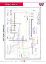
Page 18: ...18 www p light com established 2000 Wiring diagram Hydro 1 3 Valve Hydro 1 3 Valve...

Page 19: ...r Control Valve Y11 CC Dir Control Valve Z11 CC Valve 2 Dir Control Valve Y11 CC Dir Control Valve Z11 CC Valve 3 Dir Control Valve Y11 CC Dir Control Valve Z11 CC Sandwich Sandwich Locking Valve A B...

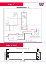
Page 20: ...20 www p light com established 2000 Wiring diagram Hydro P T Hydro P T T T P P Hydraulic connections P T Hydro with P T...

Page 21: ...el 46 472 483 93 Viktigt Important Wichtig T rke Vor dem Testen Hydraulik l auff llen Empfehlung Hydraulik l ISO VG 32 Empfehlung Achs l ISO VG 15 Service und Fehlerbehebung Ziehen Sie das Servicehand...

Page 22: ...ections T B1 B2 and B3 Hydraulic connections P A1 A2 and A3 Main breaker Stainless steel box with charger and electronics Battery 120Ah Hydraulic oil filling Tank 13 liters 879 290 285 428 440 Hydraul...

Page 23: ...ns T B1 B2 and B3 Hydraulic connections P A1 A2 and A3 Main breaker Battery 150Ah Hydraulic oil filling Tank 13 liters Stainless steel box with charger and electronics 428 440 477 7 285 290 879 487 Hy...

Page 24: ...ons T B1 B2 and B3 Hydraulic connections P A1 A2 and A3 Main breaker Battery 150Ah Hydraulic oil filling Tank 13 liters Stainless steel box with charger and electronics 428 879 477 7 465 5 487 285 290...

Page 25: ...nnections T B1 B2 and B3 Hydraulic connections P A1 A2 and A3 Main breaker Battery 200Ah Hydraulic oil filling Tank 13 liters Stainless steel box with charger and electronics 428 478 285 290 1079 Hydr...

Page 26: ...tions Switch Mom 30 Switch Mom 32 Main breaker Main breaker Hydraulic oil filling Tank 22 liters Hydraulic connections T B1 B2 and B3 Hydraulic connections P A1 A2 and A3 Battery 200Ah Stainless steel...

Page 27: ...Li axle Ground Gnd 3 CAN H ej f r EBS eller ABS CAN L ej f r EBS eller ABS 1 Ground GND for pin 1 3 and 5 12 2 Indica on of applied parking brake due to loss of air pressure 3 Ground GND f r pin 14 an...

Page 28: ...www innonet se P LIGHT Control unit Manufactory No Trailer Company City Country Sign Manufactory date Fill in and attach with the vehicle trailer that P LIGHT is mounted on Electric box No Serial No...

Reviews: