Last update: 03/11/2011
2
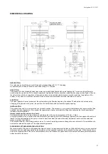
DIMENSIONAL DRAWING
DESCRIPTION
The valve has an inlet fitting, an outlet fitting and a bypass fitting with G ½” F threading.
A pneumatic jack is fitted to the valve with a feed fitting G ¼” F thread.
SELECTION
This product is to be utilized with clean fresh water, even slightly additivated with normal detergents.
For use involving different or
corrosive liquids, contact the PA Technical department.
Appropriate filtration should be installed when using unclean liquids.
Choose
the valve in line with the running data of the machine where to be installed (rated pressure, max flow and max temperature of the
system). In any case, no machine overpressure has to exceed the permissible pressure imprimed on the valve.
FUNCTION
The valve regulates the max pressure of the system altering the flow discharged by the bypass. The adjustment is carried out by
changing, through means of a piston, the position of a shutter that partially closes the bypass opening.
INSTALLATION
This product is bound to be incorporated on a finished machine. This accessory, on a machine that produces hot water must be fitted
upstream to the heat generator. On a system that generates hot water, anticipate the fitting of accessories that limit the accidental
increase of fluid temperature.
Always install a safety valve in the circuit.
The pneumatic jack has to be fed with dry air and lubricated to the maximum pressure of 10 bar – 1 Mpa.
It is recommended to use a nozzle with a flow rate that at gun opening, permits to discharge regularly from the bypass of the valve at
least 5% of the flow supplied by the pump in order to have a constant pressure value, easy adjustment and to avoid troublesome
pressure spikes at gun closure.
If the nozzle wears out, the working pressure drops. To revive the working pressure, change the worn out nozzle. On installation of a
new nozzle, re-adjust the system to the original working pressure.
DISCHARGE SYSTEM AND WATER ADDUCTION
We recommend to fit the valve with bypass discharge to a tank. It is advisable that the tank be fitted with deflectors to reduce eventual
turbolence and air bubbles generated by the immission of the bypass flow which could be harmful for the pump. With elevated flow or
near to the maximum flow of the valve, the installation with a recirculation of bypass direct to the pump could cause potential pressure
spikes harmful to the pump.
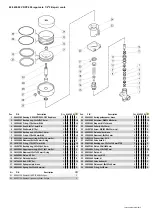
Summary of Contents for VRPP 600
Page 6: ...__ NOTE NOTES...
Page 7: ...__ NOTE NOTES...


