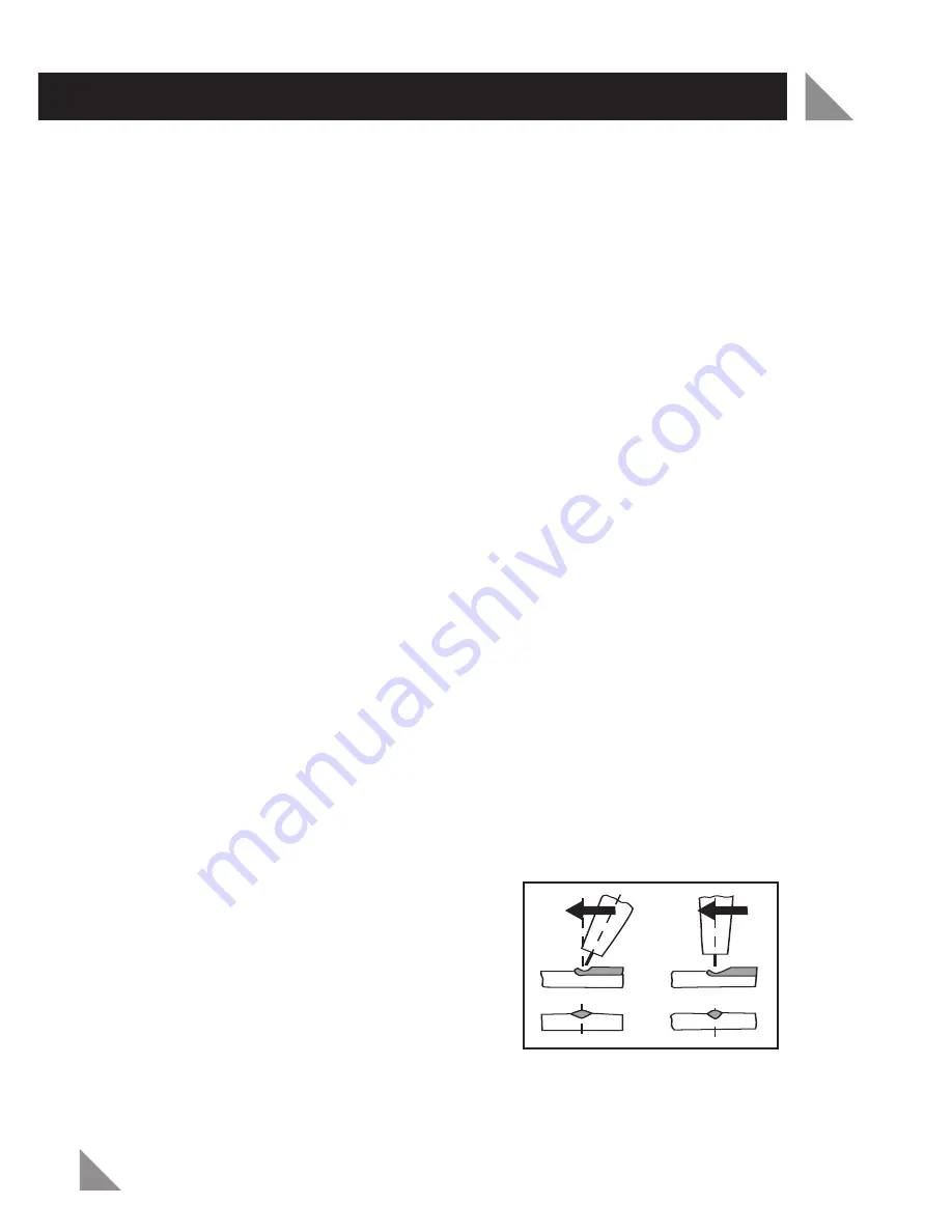
background image

OPERATION (cont.)

8

Fig 1

9.   Take your welding tip and thread over the wire and screw onto the gun. Take 

your shroud and screw over the welding tip. Using pliers to cut flush with 
shroud end.

Position the two pieces of metal you wish to join.

Hold the mig torch approximately 2 cm away from the desired join area. Lower
or hold the welding mask over your face. Using the mig torch, proceed to
strike the wire tip against the desired join area on the work piece as if you are
striking a match. This is the correct strike up method. 

Note:

Hitting the electrode on the work piece can damage the electrode and

make strike up difficult.

1. The welding power source has two main control settings. These are the wire

speed control and the current (amps) control.

2. The combination of these settings requires alteration depending on the

material and other conditions that affect the weld. It is advisable to practice
on scrap pieces of material to clarify which settings are going to give you the
best weld.

3. The wire speed and current control needs to be set at the correct speed and

power for a smooth and a consistent weld. There are many variables that
affect the weld including the style, speed of the operator, the material being
welded and the diameter of the wire.

4. When welding with large diameter wire it is advisable to use the high amps

setting selector on the front of the welder.

5. When welding with thinner diameter wire it is advisable to use the low amps

setting selector on the front of the welder.

If the Wire Speed is set too fast “stubbing” will occur as the wire dips into the
molten pool and does not melt. Welding in there conditions normally produces a
poor weld due to lack of fusion. If however the welding speed is too slow, large
drops will form on the end of the electrode wire, causing splatter. The correct
setting of wire speed can be seen in the shape of the weld deposit and heard by a
smooth regular are sound.

3.

Postion of MIG Torch

The angle of MIG

torch to the weld has an effect on the
width of the weld run. Refer to Fig 1.

4.

Distance from the MIG Torch Nozzle to
the Work Piece

The electrode stick out

from the MIG Torch nozzle should be
between 2.0mm to 5.0mm. This distance
may vary depending on the type of joint
that is being welded.

Forehand

Vertical

Summary of Contents for OZMW90A

Page 1: ...MIG WELDER 90 Amps MODEL NO OZMW90A OPERATING INSTRUCTIONS Always Wear Eye Face Ear Protection www ozito com au...

Page 2: ...s Overload protection Portable Accessories included Handle SPECIFICATIONS MODEL NO OZMW90A 2 1 Carry Handle 2 Welding Mask 3 Mig Torch 4 Shroud 5 Control Switches 6 Wire Brush 7 Earth Clamp 8 On Off S...

Page 3: ...anual and a little practice to obtain a professional finish in welding car bodywork and many other uses for which you ll find it ideal This welder produces a direct current output A C with a static fl...

Page 4: ...always unwind the lead completely Use of an extension lead not suitable for the power input of the equipment or which is damaged or defective may result in a risk of fire and electric shock 1 Keep wo...

Page 5: ...tive parts repaired or replaced by an Ozito Authorised Service Agent Never attempt any repairs yourself 12 Unplug the equipment Unplug the equipment when it is not in use before changing any parts acc...

Page 6: ...welding circuit Do not use the welder to defrost piping Ensure the welder is placed on a level surface to prevent overturning Provide adequate ventilation or a means for removal of the welding fumes p...

Page 7: ...a non conductive surface non metal e g a dry wooden bench 6 Unscrew the shroud on the end of the mig torch and remove the welding tip Turn the machine onto wire speed feed only and the speed dial onto...

Page 8: ...set at the correct speed and power for a smooth and a consistent weld There are many variables that affect the weld including the style speed of the operator the material being welded and the diamete...

Page 9: ...nger glowing Remove using the combination wire brush and chipping hammer provided in the kit Electricity The electricity flows through the wire to the attached torch The electricity will not leave the...

Page 10: ...ire speed and it should be Starting to weld Increased or if t gives an erratic sound with possibly a feel that the wire is stubbing against the work and excessive spatter you have too much wire speed...

Page 11: ...of spatter Replace the tip regularly as a good electrical contact between the top and wire is essential Avoid kinking the torch and never use it to pull the machine around to ensure the wire passes fr...

Page 12: ...uency use If the product has been operated on a supply voltage other than that specified on the product If the product shows signs of damage or defects caused by or resulting from abuse accidents or a...

Reviews: