


2. ARC WELDING ASSEMBLY
3. ARC WELDING
Slag
Slag is refuse left around the weld
after welding, this should only be
removed after the weld has cooled
down and is no longer glowing.
Face shield must be worn during
removal of slag.
4. Install thin (uncoated)
end of Electrode into the
arc electrode holder.
5. Attach the Earth Clamp
to the work piece
ensuring area is free
from paint or dirt so that
there is a good electrical
connection.
3. Attach Earth Clamp lead
to the NEGATIVE (-)
output terminal. Insert &
rotate until connection is
firm.
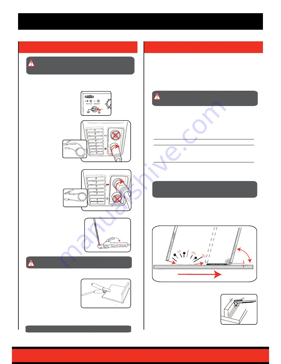
70-80º
Strike
Keep Consistant
Height
2.0mm
Welding Direction
ARC
2. Attach Arc Electrode
Holder lead to the
POSITIVE (+) output
terminal. Insert & rotate
until connection is firm.
1. Set Process Selection
Switch to ARC
WELDING process.
Preparation
Before welding ensure that:
•
You have read and understand the safety section of this
manual.
•
There is sufficient ventilation, particularly at the front and rear
of the unit.
•
You have an adequate fire-fighting devices on hand.
Electrodes & Welding Current
The welding current must be regulated in accordance with the
diameter of the electrode and the thickness of the steel being used.
This will vary with the type of electrodes and material you are using.
Below is a guide suggesting suitable currents & thickness for welding
steel.
Electrode Diameter
Welding Current (Amps)
Thickness of Steel
1.6mm
35 - 45
1.5 - 2mm
2.5mm
60 - 100
2 - 4mm
3.2mm
100 - 130
3 - 6mm
6. Connect the Inverter welder power cord into a power outlet.
Striking the Arc
Lower the electrode slowly and proceed to strike the electrode tip
against the desired join area on the work piece as if you are striking
a match. As soon as you have the arc, try to maintain a distance
from the work piece equal to the diameter of the electrode being
used, eg 2.0mm electrode, 2.0mm gap.
WARNING!:
ENSURE THE TOOL IS DISCONNECTED
FROM THE POWER SUPPLY BEFORE PERFORMING
ANY OF THE FOLLOWING OPERATIONS.
Before starting you will require a suitable Electrode according to the
specific material type and thickness.
WARNING!:
ENSURE ALL OIL, PETROL AND
FLAMMABLE CONTAINERS HAVE BEEN REMOVED
FROM WELDING AREA.
CAUTION!:
Ensure approved protective clothing and
welding helmet/mask is worn at all times to protect
your face and eyes from arc UV radiation and sparks.
WARNING!:
Do not touch the electrode while the
welder is turned on
NOTE:
Avoid use of long extension leads.


