background image


14 

Oxford Technical Solutions


RT-Range 

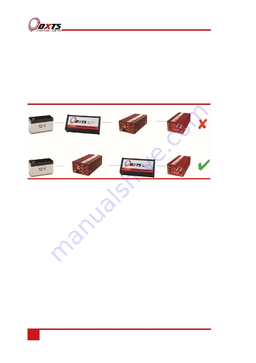
When using the RT-UPS with RT-Range S or standard RT-Range products, care should 
be taken when connecting the systems. The RT-UPS should be connected between the 
RT-Range Hunter system and the RT. It should not be connected between the power 
supply and the RT-Range Hunter system as the current draw will be too much and may 
damage the RT-UPS. Figure 4 illustrates the correct connection set up. 

Figure 4. Connection set-up with RT-Range or RT-Range S 


Summary of Contents for RT-UPS

Page 1: ...Confidently Accurately RT UPS Uninterruptible Power Supply User Manual ...

Page 2: ...ll brand names are trademarks of their respective holders The software is provided by the contributors as is and any express or implied warranties including but not limited to the implied warranties of merchantability and fitness for a particular purpose are disclaimed In no event shall the contributors be liable for any direct indirect incidental special exemplary or consequential damages includi...

Page 3: ...ct repair at an authorised location only Determination of replacement or repair will be made by Oxford Technical Solutions Limited personnel or by personnel expressly authorised by Oxford Technical Solutions Limited for this purpose In no event will Oxford Technical Solutions Limited be liable for any indirect incidental special or consequential damages whether through tort contract or otherwise T...

Page 4: ...cting and disconnecting the internal battery 8 Connections 12 Operation 13 LED definitions 13 Extended storage 13 RT Range 14 Specification 15 Conformance notices 16 Regulator testing standards 16 Safety notices 17 Battery information 17 Transport by sea 18 Transport by air 18 Disposal End of Life 18 Revision history 19 ...

Page 5: ... UPS continues to output a constant 12 volts for up to two minutes using its internal battery This prevents brown outs during vehicle cranking and black outs if the auxiliary power socket is accidentally disconnected In this way the INS continues to operate and there is no need to re initialise or perform additional warm ups When the input power supply is absent a warning buzzer will sound and the...

Page 6: ...f the battery temperature exceeds approximately 65 C charging will be suspended until the temperature falls to around 60 C If the battery temperature falls below approximately 0 C charging will be suspended until the temperature reaches approximately 5 C If the battery temperature approaches the lower threshold the fan is temporarily disabled to avoid unnecessary cooling that might prevent chargin...

Page 7: ...ser Manual Revision 150609 7 Scope of delivery Table 1 lists the parts that are delivered with an RT UPS Table 1 Summary of components delivered with an RT UPS Qty Description 1 RT UPS unit 1 RT UPS user manual ...

Page 8: ...nects and disconnects the internal battery In normal operation the switch should remain in the on position I however when being transported by air the switch should be set to the off position 0 to isolate the battery Older versions of the RT UPS require some disassembly in order to access the battery Although the RT UPS does not need to be opened in a full electrostatic free environment you should...

Page 9: ...RT UPS User Manual Revision 150609 9 Figure 1 Removing the front panel screws on the older model RT UPS Remove the front panel and slide the lid off the RT UPS as shown in Figure 2 ...

Page 10: ... The connector can only be fitted one way round take care not to force it incorrectly Slide the lid back in place fit the front panel and replace the four screws The battery will now be connected correctly Before transporting by air disconnect the battery The battery should only be replaced by OxTS because the temperature sensor needs to be fitted correctly ...

Page 11: ...RT UPS User Manual Revision 150609 11 Figure 3 Battery connector fitted correctly ...

Page 12: ...Manufacturer Littelfuse Part Number 0214005 Description 5 A Torpedo Type Fuse Dimensions 25 6 mm Ø Voltage Rating 36 V Table 3 Input power lead pin configuration Pin Direction Description 1 Input Power in 9 48 V dc This pin is the tip of the connector red wire 2 Input Input ground black wire Connector Automotive universal fused auxiliary power plug cigar lighter plug Table 4 Output power lead pin ...

Page 13: ...finitions Table 5 lists the definitions of the LEDs on the RT UPS As a special condition all LEDs flash when the RT UPS has overheated Table 5 LED definitions LED label Description No power Lit when there is no power available in the internal battery to supply the output Discharging Lit when power is being supplied from the internal battery Charging Lit when charging Flashing at 1 Hz means fast ch...

Page 14: ...ng the systems The RT UPS should be connected between the RT Range Hunter system and the RT It should not be connected between the power supply and the RT Range Hunter system as the current draw will be too much and may damage the RT UPS Figure 4 illustrates the correct connection set up Figure 4 Connection set up with RT Range or RT Range S ...

Page 15: ... protection Yes Supply reversal protection Yes will blow fuse Dimensions mm 170 81 48 excluding cables Weight 0 9 kg including cables Operating temperature range 10 50ºC Internal over heat temperature 75ºC typical Upper charging temperature 65ºC typical Lower charging temperature 0ºC typical Environmental protection None 1 The 9 V minimum operating voltage is defined at the connector end of the in...

Page 16: ... equipment does cause harmful interference to radio or television reception which can be determined by turning the equipment off and on the user is encouraged to try to correct the interference by one or more of the following measures Re orient or relocate the receiving antenna Increase the separation between the equipment and the receiver The RT UPS conforms to the requirements for CE Regulator t...

Page 17: ...ains a battery Do not burn The enclosure will become warm while in use allow heat to be ejected from the enclosure Do not dispose of in domestic waste Do not ingest the battery Do not allow the product to become wet or immersed in water Recommended storage temperature 20 C Battery information In the event of a faulty battery a replacement can be sent out from OxTS on request along with instruction...

Page 18: ...nce with local and state regulations Transport by sea For sea transportation of nickel metal hydride round cells there is an additional requirement 1 Batteries must not be stored in close proximity of external heating sources Transport by air Any electrical battery or battery powered device equipment or vehicle having the potential of a dangerous evolution of heat must be prepared for transport so...

Page 19: ...ly 110607 First release 130613 Updates discharge time reduced to one minute 131125 Minor updates RT Range disclaimer 140211 Changed input power lead wire colours Added note about replacement battery 141204 Updated to show improved discharge specification notes to advise on operation 150609 Updated for new battery isolation switch ...

Reviews: