


04
FEATURES & USAGE NOTES
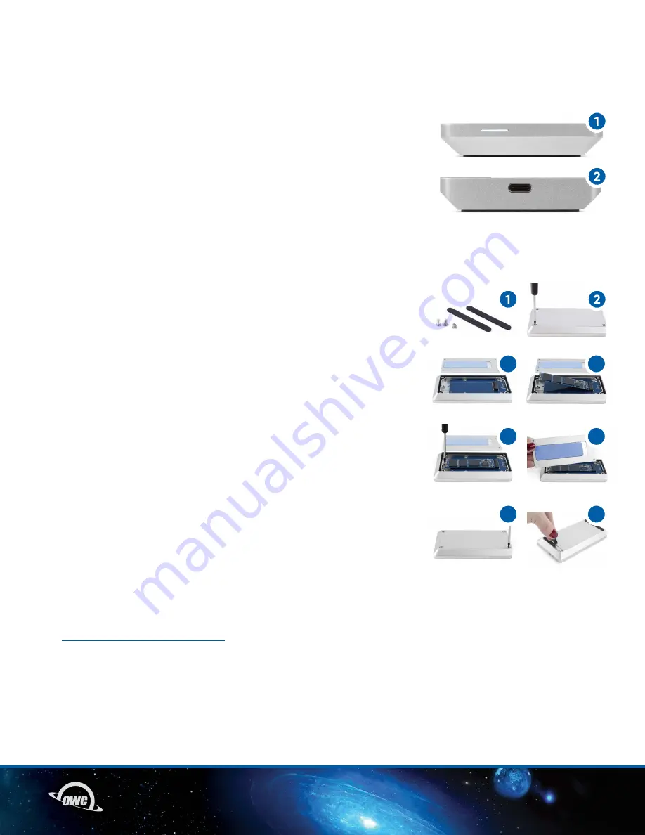
2.1 ENCLOSURE FEATURES
1. LED Indicator – This LED emits a solid white light when the Envoy Pro
is powered on and flashes during drive activity.
2. USB 3.1 Gen 2 port – Attach the included USB 3.1 Gen 2 cable here.
FEATURES & USAGE NOTES
2.2 DRIVE ASSEMBLY
1. Remove the enclosure (in the protective foam bag) and the screw packet
from the box. The packet should contain two drive enclosure screws, one
drive mount screw, and two rubber feet.
2. Remove the enclosure from the foam bag, turn the enclosure over then
remove the two screws secured at opposite corners. Set the screws aside.
3. Remove the bottom cover. Note that the underside has a thermal pad;
the orientation of the cover will be important later.
4. Set the top portion of the enclosure on a static-free work surface, face
up, then align the M.2 SSD connector with the black PCIe connector on the
Envoy Pro’s circuit board. Carefully seat the drive into the connector.
5. Using the shorter drive mount screw from the packet, carefully secure
the M.2 SSD to the drive post.
6. Reseat the bottom cover onto the top portion of the enclosure. Make sure
the small cutout section where the thermal pad is, rests above the PCIe
connector, not the drive mount screw.
7. Using the two screws removed in Step 2, plus the two remaining screws
in the packet, secure the bottom cover to the top portion of the device.
The cover should sit completely flush at the end of this process.
If any edge or corner sits slightly above
the others remove the screws, make sure the thermal pad is oriented
correctly and then re-affix the screws.
8. Last, take the two rubber feet, remove the adhesive strip from each, and
place each over the cutouts on the bottom cover, as shown.
For tips on formatting your new drive please visit:
www.owc.com/support/formatting
2.3 USAGE NOTES
-With prolonged use, the drive case may be warm to the touch. This is normal.
3
4
5
7
6
8


