background image

Installation

2

OWC Data Doubler

2.1 Disassembling the Mac mini

Due to the number and variety of screws involved in this process, we commend you use a device to  
organize and keep track of the screws, such as an ice cube tray. This will help you to put the screws back in 
the correct locations.

INSTALLATION

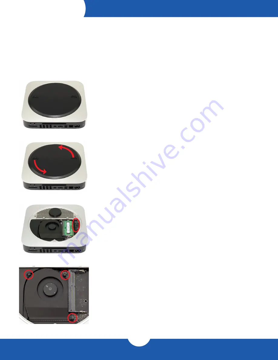
1.  Place the Mac mini upside down, as shown. Use a soft surface such as a towel 

or a mouse pad in order to protect the Mac mini from scratches.

2.  Rotate the bottom cover counterclockwise to the unlocked position, as shown in the 

picture to the left. There is a white dot on the bottom cover. When the bottom cover 

is unlocked, this white dot will line up with the corresponding dot on the aluminum 

housing. When the bottom cover is unlocked, press on one side of the cover to cause 

the opposite side to pop up, then remove it.

3.  Remove the two memory modules. The instructions for removing the memory modules 

are printed directly to the right of the memory inside the Mac mini, as circled in the 

picture to the left.

4.  Remove the three Torx T6 screws that secure the fan, as circled in the picture  

to the left. The two top screws are shorter; the screw on the lower right is a longer 

standoff screw.

Summary of Contents for data doubler

Page 1: ...D A T A D O U B L E R Apple Mac mini Assembly Manual User Guide...

Page 2: ...uter Compatibility Drive Compatibility 1 2 Package Contents 1 1 3 About This Manual 1 Installation 2 1 Disassembling the Mac mini 2 2 2 Installing the Data Doubler 8 Support Resources 3 1 Troubleshoot...

Page 3: ...Functions and features may be different from those stated in this manual Please visit the product web page for the most recent product specifications OWC Data Doubler kit includes mounting screws Five...

Page 4: ...unlocked position as shown in the picture to the left There is a white dot on the bottom cover When the bottom cover is unlocked this white dot will line up with the corresponding dot on the aluminum...

Page 5: ...ockwise as shown in the picture to the right When removing the cowling be careful not to catch it on any other hardware 6 Remove the short T6 screw at the bottom of the black plastic cowling as circle...

Page 6: ...t the cable connector directly up The nylon pry tool or a pair of tweezers may help 11 Disconnect the hard drive flex cable and the optical drive flex cable as shown in the pictures to the right Use t...

Page 7: ...ure to the right Wiggle out the connector with either your fingers or the nylon pry tool A pair of tweezers may also help 17 Now that all the cables are disconnected slide the logic board assembly the...

Page 8: ...he picture to the right 21 Remove the power supply by pulling it straight out of the housing as shown in the picture to the left You may need to rotate the power supply slightly to the left 22 Slide t...

Page 9: ...e optical drive and the carrier Simply slide the cable up and out of the way as you go about the process of removing the optical drive 27 Remove the four T8 screws from the optical drive as circled in...

Page 10: ...ert the two included Phillips screws into the drive through the screw holes in the Data Doubler as shown at right 4 Insert the Data Doubler into the optical drive carrier as shown in the picture to th...

Page 11: ...ical drive and the cable can be damaged easily Note the position of the cable on the optical drive When you move the cable to the Data Doubler you want to match the position as closely as possible in...

Page 12: ...stall the T6 screw that secures the optical drive carrier to the housing as circled in the picture to the left 13 Slide the hard drive into the housing as shown in the picture to the right There are t...

Page 13: ...into the hard drive If so simply move the logic board so that it clears the hard drive Do not slide the logic board all the way in Leave some space as shown to the right 19 Connect the power supply c...

Page 14: ...ws circled in the picture to the right Remember the screw at the bottom and the two outside screws at the top are 2mm hex screws but the Torx T8 screwdriver will fit Be careful not to exert too much f...

Page 15: ...ith your thumbs until it locks into place as shown in the picture to the right The assembly process is now complete You can now enjoy the use of a second hard drive or solid state drive in your Mac mi...

Page 16: ...seen in Finder check Disk Utility to see if the drive is recognized by the computer In Windows check in Disk Management If the drive is seen there it may need to be formatted www owc com format If pr...

Page 17: ...suant to Part 15 of the FCC Rules These limits are designed to provide reasonable protection against harmful interference in a residential installation This equipment generates uses and can radiate ra...

Page 18: ...Do not place heavy objects on top of the device Protect your device from excessive exposure to dust during use or storage Dust can build up inside the device increasing the risk of damage or malfuncti...

Reviews: