

–4–
–5–
–6–
http://support.overlandstorage.com
You can get additional technical support on the Internet at the
Overland Storage Support web page
by contacting Overland Storage using the information found on the
page on our web site.
OD11016
©2014-15 Overland Storage, Inc.
Step 5
Cable Attachment
CAUTION:
The speed/duplex setting on a SnapScale defaults to autonegotiate. The
networking switch or hub to which the unit is connected must also be configured to
autonegotiate; otherwise, network throughput or connectivity to the unit may be
seriously impacted.
IGMP Snooping should always be turned off in switches used for the SnapScale storage
network. Refer to the Snap Network Configuration Guide for complete details.
1.
Verify that all
client
and
storage switches
are connected to a UPS.
For failover, verify that the two
storage switches
are plugged into different UPS
units connected to different power sources.
2.
Using the two included 1Gb cables or two optional 10Gb cables, connect the
Client Ethernet
ports on the node to the Client switch.
1
3
2
1 - AC Power
2 - USB 2.0 Ports (4 total)
3 - VGA Port*
4 - Serial Port*
5 - Ethernet 1 Port (Client)
6 - Ethernet 2 Port (Client)
7 - Ethernet 3 Port (Storage)
8 - Ethernet 4 Port (Storage)
9 - SAS Card Port
*
For use by Technical Support only.
4
2
6
9
1Gb Version
7
8
5
1
3
2
1 - AC Power
2 - USB 2.0 Ports (4 total)
3 - VGA Port*
4 - Serial Port*
5 - Ethernet 1 Port (Client)**
6 - Ethernet 2 Port (Client)**
7 - Ethernet 3 Port (Storage)**
8 - Ethernet 4 Port (Storage)**
9 - SAS Card Port
*
For use by Technical Support only.
4
2
9
10Gb Version
5
6
7
8
**
May feature the optional SFP+ card.
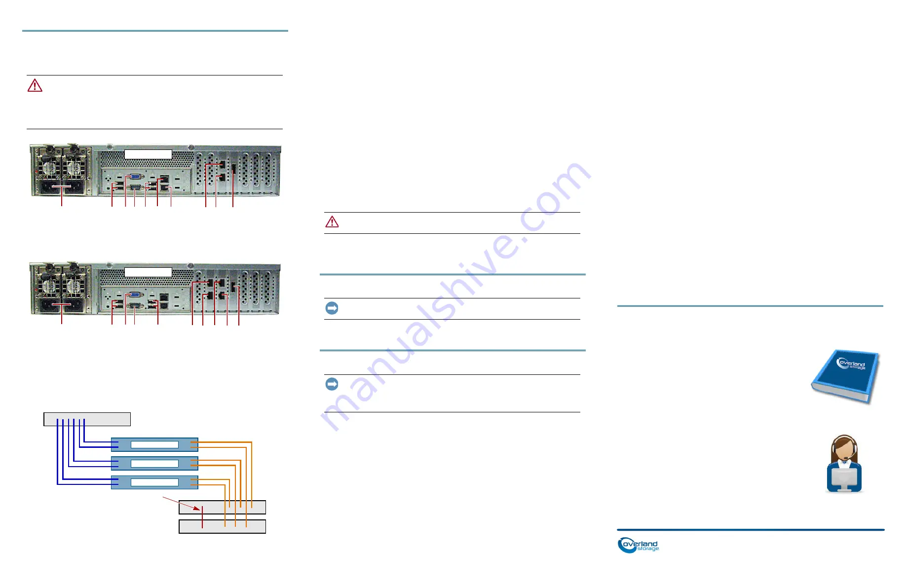
Client Switch
Storage Switch
Storage Switch (Failover)
SnapScale Node
SnapScale Node
Ethernet Cable Connecting Switches
SnapScale Node
SnapScale Node
3.
Using an included 1Gb cable or a customer-supplied 10Gb cable, connect one
Storage Ethernet
port on the node to one of the Storage switches.
NOTE: The storage-side network must be isolated and exclusive to the cluster.
4.
Using an included 1Gb cable or an optional 10Gb cable, connect the other
Storage
Ethernet
port on the node to the other Storage switch (for failover).
5.
Connect the two Storage switches using an included 1Gb cable or an optional
10Gb cable.
6.
Attach both supplied
power cords
to the AC power sockets on the node and the
other ends to
different UPS
units.
NOTE: SnapScale nodes are designed to work with APC-brand USB or network-based UPS
devices to automatically shut down cleanly in the event of a power failure. Refer to the
SnapScale Administrator’s Guide for detailed information on their use.
7.
Briefly press the front
power switch
to power on the node.
Important – Read This Before Continuing
After initial power up with new drives, a SnapScale node can take up to
10 minutes
to
complete the new node initialization process. During this time, the Status LED flashes
an alternating green and amber pattern.
CAUTION:
Under no circumstances should power be removed while the system is in
this state! Doing so may render the node inoperable.
Once initialization is complete, the system automatically reboots and the Status LED
displays a solid green color.
Step 6
IMPORTANT: A minimum of three (3) nodes are required to create a SnapScale cluster.
All the nodes must be installed and powered on before attempting to create the cluster.
When all the nodes are installed and ready, continue with
.
Step 7
IMPORTANT: SnapScale nodes are configured to acquire an IP address from a DHCP
server on the client network. If no DHCP server is found on the network, the node
defaults to an IP address in the range of 169.254.xxx.xxx. You may not be able to see
the node on your network until you discover and optionally assign an IP address.
NOTE: Alternately, you can use SnapServer Manager (SSM) to locate the new nodes. Refer to
Using SnapServer Manager to Connect (Alternate Option)
.
This procedure requires that name resolution services (via DNS or an equivalent
service) be operational.
1.
Check the Find Me label to get the
node name
.
The default node name is “NODE
nnnnnnn
,” where
nnnnnnn
is the node number.
The node number is a unique, numeric-only string that appears on a label affixed
to the top rear of the node.
2.
In a web browser, enter the
node name as the URL
.
For example, enter “http://NODE9876543” (the default SnapScale node name).
3.
Press
Enter
to connect to the Web Management Interface.
4.
In the login dialog box, enter “
admin”
as the user name and “
admin”
as the
password, then click
OK
.
5.
Complete the
Initial Setup Wizard
to either create a new SnapScale cluster or
join an existing cluster.
6.
At the end of the setup wizard, you are given an opportunity to
register
your
cluster.
Follow the on-screen instructions. Technical and warranty support are
not
available
until the warranty is active.
Your SnapScale cluster is ready to be configured for your specific environment.
Using SnapServer Manager to Connect (Alternate Option)
NOTE: If necessary, SnapServer Manager (SSM) can be used to connect to the nodes.
SnapServer Manager is an administrative application that provides administrators a
single interface from which they can discover any SnapServer, SnapScale cluster, or
Uninitialized node on the network. You can download and install SSM from:
http://docs.overlandstorage.com/ssm
Install SSM on a computer residing on the same network segment as your nodes.
1.
Launch
SSM
.
SSM discovers all SnapServers, SnapScale clusters, and Uninitialized nodes on its
local network segment and displays their information. If you do not have a DHCP
server, there might be a delay before the items appear on the network.
NOTE: To distinguish multiple Uninitialized nodes, you may need to find their default node
names as explained in the previous procedure.
2.
In SSM, right-click the
node name
, and select
Launch Web Administration
.
3.
Log into the
Web Management Interface
.
Enter “
admin
” as the user name and “
admin
” as the password, then click
Login
.
4.
Complete the
Initial Setup Wizard
and
Registration
process.
Your SnapScale cluster is ready to be configured for your specific environment.
Step 8
User Guides
For detailed information on cabling and configuring your
SnapScale nodes, or adding more nodes to a cluster, refer to
the
SnapScale Administrator’s Guide
or the
RAINcloudOS
Release Notes
. They are
available online
at:
http://docs.overlandstorage.com/snapscale
Translated versions of this Quick Start Guide are also
available on the web page.
Warranty and Technical Support
For warranty and general technical support information,
see our
Contact Us
web page:
http://www.overlandstorage.com/company/contact-us/
index.aspx
For information on contacting Overland Technical Support,
see our
Contact Support
web page:


