

Quick Start Guide
–1–
–2–
–3–
SnapScale X2
®
2U Node
Step 1
It is
essential
that you activate your warranty for each SnapScale node. Technical and
warranty support are
not available
for the nodes until the warranty is active:
1.
http://www.overlandstorage.com/
and select
Service & Support > Sign-in To My Account
.
2.
, enter your
e-mail address
and
password
, and click
GO
.
3.
Click
Register New
.
4.
Fill in the information and click
Submit
.
As a registered user, your basic data is entered automatically. Only the serial
number must be entered. This speeds up registering multiple nodes.
Your warranty certificate will be emailed to you. Follow the instructions included in
the email to complete the registration process.
Step 2
WARNING:
To reduce the risk of electric shock or damage to equipment, always
remove any power cords while working with the unit.
AVERTISSEMENT:
Pour réduire le risque de choc électrique ou endommagement de
l'équipement, retirez toujours les cordons électriques en travaillant avec l'appareil.
Unpack the unit placing it and the drives on a secure surface. Remove the blue plastic
film. Any optional internal components, such as expansion cards and extra memory,
need to be installed before continuing. Refer to the installation instructions and
warnings that are packaged with the add-on components.
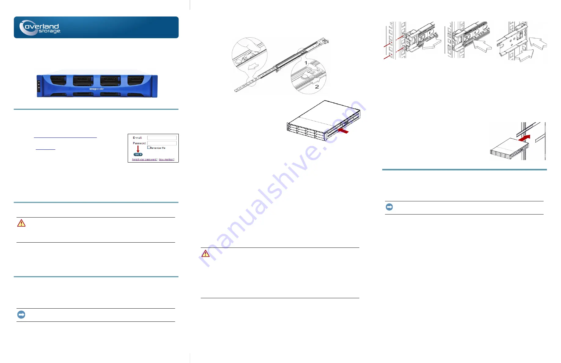
Step 3
The SnapScale X2 comes with a sliding rail rack kit for easy installation into a 19-inch
(EIA-310) rack. The two inner rails are identical; install them with their front ends
pointed toward the front of the node.
IMPORTANT: Two-post telco-style or other racks less than 29 inches in depth will NOT
support this unit.
Attach Inner Rails to Unit
1.
Select a
rail assembly
and slide the inner rail out until it stops.
Enter
Enter
2.
Push the inner rail
release latch
forward and remove the inner rail.
3.
To retract the
middle rail
, release the lock (1) and slide the middle rail into (2)
the outer rail.
4.
other rail
assembly
.
5.
Align the
inner rail
against the side of
the
node
.
6.
Using the supplied
screws
, secure the
rail.
7.
other inner
rail
.
Optional Steps for Thicker Rack Rails
For standard rack rail sizes 3mm or less, skip this procedure and proceed to
Outer Rails to Square-holed Rack.”
For racks with rails
thicker than 3mm
, the sliding rail anchors cannot be seated
without exerting excessive force and possibly damaging the sliding rail kit. The
brackets must be removed from each end of the rails to make the anchors seat securely:
1.
Locate the
bracket
at the end of a slide rail and remove the
screw
securing the
bracket to the rail.
2.
Pushing the
bracket
toward the end of the rail, pry the back of the
bracket
upward to unseat and remove it.
3.
other end
of the rail.
4.
other rail
.
5.
Use the
two supplied screws
to secure the
rear ends
of the rails to the rack.
Attach Outer Rails to Square-holed Rack
WARNING:
It is recommended that a mechanical lifter (or at least two people) be
used to raise and align the unit to prevent injury during installation. Use care when
inserting or removing a unit into or out of a rack to prevent the accidental tipping of
the rack, causing damage or personal injury.
AVERTISSEMENT:
Afin d’éviter des blessures pendant l’installation, il est
recommande d’utiliser un monte-charge (ou au moins deux personnes) pour élever ou
aligner l’appareil. Faites attention lorsque vous insérez ou retirez l’appareil d’un
support, pour empêcher le déversement accidentel de la crémaillère causant des
dommages et des blessures.
1.
Position the front of one of the
rails
in line with the front vertical rail mounting
holes (1) and move it forward until the
rail anchors
are through the holes.
2.
Push the rail toward the
outside of the rack
(2) until the rail locks snap into
place.
3.
At the
rear
(3), slide the outer rail in or out (a) to fit between the vertical rails on
that side and then repeat
to secure it (b).
Make sure the rear holes are the same height as the front holes so the rail is level.
4.
For the
other rail
Make sure this rail is mounted at the same height as the first rail.
Install in Rack
1.
Using the mechanical lifter, position the
node
in
front of the rack.
2.
Insert the
inner rails
into the
middle rails
and slide the unit into the rack.
3.
Using
four
of the
provided screws
, secure the
SnapScale to the front of the rack.
Step 4
The SnapScale X2 comes with eight blank drive carriers installed (drives are sold
separately). As many as 12 disk drives can be installed leaving blank drive carriers
filling in any empty bays.
IMPORTANT: To maintain proper airflow and cooling, a drive assembly or a blank drive
carrier must be installed in
every
bay. No empty bays are allowed.
Install Drives
NOTE: Do not remove the disk drives from their carriers. Doing so voids the drive warranty.
Once the SnapScale node is in the rack, install the drives as follows:
1.
Remove any
blank drive carriers
from the bays that will be used for drives.
2.
Starting at the top left, position a
drive assembly
in front of a
bay
.
3.
Slide the
assembly
in until it stops.
4.
Push in the
latch
until it clicks, locking the assembly in the bay.
5.
for
each
remaining drive assembly.
Attach the Bezel
1.
Position the bezel with the top and bottom edges aligned with the top and bottom
bezel slots
on the front of the node.
2.
Push the
bezel
toward the unit until the magnets on the ends connect and the
bezel snaps into place.
3.
Verify that the bezel is
aligned
properly with all the LEDs visible and the Power
Panel on the left side is in line with the hole on the bezel flange.
1
2
Rear
a
b
3
View
*10400583
002*
10400583-002


