Installing the PowerLoader (continued)
1)
Press the button four times to scroll to the Configure submenu Press
Enter to display the Configure submenu:
2)
Press the s or t buttons to scroll to the option you want to change. For
this example, scroll to Set SCSI and press Enter. The Set SCSI
Submenu displays:
3)
To change the DLT1 Bus ID, scroll to DLT1 Bus ID and press Enter.
4)
From line 4, scroll through the options and press Enter to select the
number option you want.
5)
Press the Escape button several times to return to the Set SCSI Options
submenu.
6)
Repeat this procedure for each configuration option you want to change.
Load/Unload
Unlock Door
X
Show Status Menu
Maintenance Menu
L
X
Set SCSI
Set Library Mode
Set Element Base
L
Set Data Format
Library Parity:
Library Bus ID:
6
L
Enabled
NOTE:
For complete descriptions of Configuration
Options see the User and Installation Manual P/N 104262-
102
Rack Mount Installation (if applicable)
The PowerLoader can be mounted in a standard 19-inch EIA/RETMA rack
with a depth of 24 to 30 inches.
NOTE:
The cooling fan at the rear of the drive must not be
obstructed when the drive is installed in the rack. It is
advisable to allow two inches of clearance behind the
rear panel of the module.
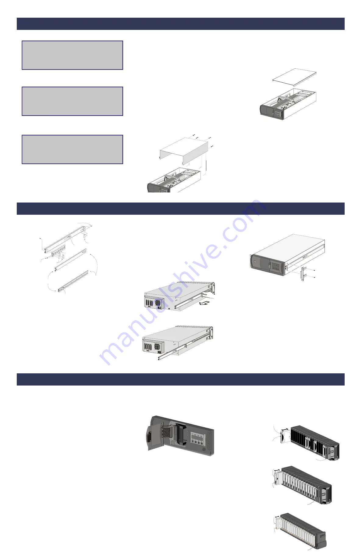
Removing the Skin
The skin is held in place by four screws at the rear panel of the
PowerLoader.
1)
Remove the four screws, slide the skin cover about one inch toward the
rear, then lift it from the chassis. Save the hardware for re-use.
1)
Refer to the figure to identify and orient the parts of the slides. The slide
is attached to the PowerLoader pem enclosure by means of three
screws through the inner slide.
2)
Separate each set of slides as follows:
•
Pull the outer slide toward the rear, along with the intermediate
slide until the inner slide lock engages the intermediate slide.
•
Continue to pull the outer slide towards the rear until the outer slide
lock engages the intermediate slide. Press down on the inner slide
lock to permit the intermediate slide to continue to move toward the
rear. Continue to move the outer and intermediate slides toward the
rear until they are separated from the inner slide.
3)
Place one of the inner slides against one side of the chassis so that the
holes in the inner slide are aligned with the holes in the chassis.
4)
Install three M4 X 8mm Phillips head pem screws through the front,
back and center holes in the inner slide into the chassis.
10-32
Screws
Nut Plate
(or 2 U-type
10-32 clips)
10-32 Low
Profile Screws
Lock Tab
Mounting
Bracket
Nut
Plates
OUTER SLIDE
INTERMEDIATE SLIDE
Rear
Front
INNER SLIDE
Lock Tab
5)
Repeat steps 3 and 4 for the other slide on the other side of the
chassis.F
Installing the Panel Extensions
NOTE:
The left and right panel extensions are alike, so
there is no risk of confusing the parts on assembly.
1)
Place a panel extension against one side of the chassis so that the holes
in the panel extension are aligned with the two holes in the chassis.
2)
Install two M4 X 8mm Phillips head pem screws through the holes in
the panel extension into the chassis.
3)
Repeat steps 1 and 2 for the other side of the chassis.
LXM-0019
Installing PowerLoader
in the Rack
Refer to the rack slides figure for parts identification.
1)
Locate the screw holes in the front and rear rails of the cabinet or
equipment rack where the PowerLoader is to be installed.
2)
Loosely assemble a mounting bracket to each outer slide, using two 10-32
screws with washers and a nut plate for each. Select slots in the mounting
brackets so the length of the assembly equals the distance between the
front and rear rails of the rack.
3)
Fasten each outer slide behind the front rail of the rack using two 10-32
screws with washers and one nut plate.
4)
Fasten each of the mounting brackets to the front of the rear rail of the
rack using two 10-32 screws and one nut plate.
5)
Tighten the screws installed in step 4.
6)
If they are not already locked, pull the intermediate slides toward the
front (out of the rack) so that they lock in the extended position.
NOTE:
This step should be performed by two people. In front
of the rack, lift the module to its installed height. Engage the
inner slides mounted on the PowerLoader with the
intermediate slides protruding from the rack, and slide the
PowerLoader toward the rack until the inner slide lock
engages the intermediate slide. This leaves the entire
PowerLoader protruding from the rack, locked in position,
supported by slides.
7)
Press inward (toward the chassis) on each of the inner slide locks to
permit the intermediate slides to move toward the rack.
8)
Slide the PowerLoader in and out several times, ensuring that the
inner and outer slide locks engage, and that the PowerLoader chassis
does not bind against the slides.
9)
If binding occurs, loosen the four screws that secure the slides to the front
rails and the four screws that secure the slides to the rear rails.
10) If necessary, repeat steps 11 and 12 until the PowerLoader chassis does
not bind against the slides.
11)
Slide the PowerLoader into the rack, and locate the proper position for
one clip nut behind the upper hole in each panel extension. Pull the
PowerLoader outward, and install 10-32 clip nuts.
12) Slide the PowerLoader into the rack, and install and tighten one 10-32
thumb screw through each panel extension into the clip nuts.
This completes the mechanical installation. Refer to the User/Installation
manual for information about electrical and SCSI connections
Inserting and Removing Cartridges
You must remove the tape magazine from the module in order to insert or
remove cartridges. When inserting cartridges, be sure that the slot you
intend to use is not already reserved in the system map for a cartridge in a
drive. The best way to avoid conflicts is to unload the drive, either through
your host computer software, or by using the Load/Unload command on the
Main Menu, described later in this chapter.
To insert or remove the magazine, make sure of the following:
•
The Control Panel is unlocked
•
The host computer must allow removal of the magazine using the
SCSI Prevent/Allow Medium Removal command. To release the lock,
exit the host software. If host computer failure prevents the host from
releasing the lock, cycle power to the PowerLoader .
If you are still unable to open the magazine door, see “Emergency Magazine
Removal”.
Installing the Top Cover
1)
Place the top cover on top of the PowerLoader with the cover's
front edge about one inch behind the front panel. Slide the top
cover forward as far as it will go. Install two of the four screws
removed when you removed the skin.
Installing the Rack Slides
NOTE:
The left and right slides are alike, so there is no risk of
confusing the parts on reassembly.
Installing the PowerLoader (continued)
Removing the Magazine
Whenever the magazine door is closed it is locked in place to prevent
tampering or accidental removal. To remove the magazine, enter the Menu
Mode by pressing the Enter button at the Default Screen. At the Main Menu,
select Unlock Door and press the Enter button. The magazine door swings
open.
Emergency Magazine Removal
If a fault occurs that prevents removal of the magazine, turn the power off for
30 seconds. Power up while continuously pressing the button. Continue to hold
the button until all of the indicators on the Control Panel light, then go out.
The door will now swing open. Release the button.
Inserting a Magazine into the Cartridge
f the magazine door on the front of the module is closed and locked, open it, as
follows. Access the Menu Mode by pressing the Enter button at the Default
Screen. At the Main Menu, select Unlock Door and press the Enter button. The
magazine door swings open. Slide the magazine through the door opening, with
the cartridges protruding from the left. When the magazine is fully inserted,
push the door closed until it locks.
.
LXL-0027
Installing the PowerLoader (continued)
Inserting Cartridges into the Magazine
Insert cartridges so that the label end with the write protect switch is
outward, with the write protect switch toward the bottom of the magazine.
After you insert the desired cartridges into the magazine, position the
magazine so the cartridges protrude to the left, and the magazine handle is
toward you. Insert the magazine into the PowerLoader with that orientation.
Write Protect
Switch
Label
Slot 1
LXL-0026a
LXL-0026e
Slot 1
Write Protect
Switch
Label
LTO
DLT/SDLT
AIT
LXL-0026d
Write Protect
Switch
Label
Slot 1
Slot 1
Label
Write Protect
Switch
Slot 1
Label
Slot 1
Write Protect
Switch


