


6
ASSEMBLY
IMPORTANT!
Whilst every care is taken in the manufacture of this product, care must be taken
during assembly in case sharp edges are present.
Please read the Important Information section carefully before assembly.
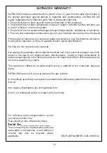
1
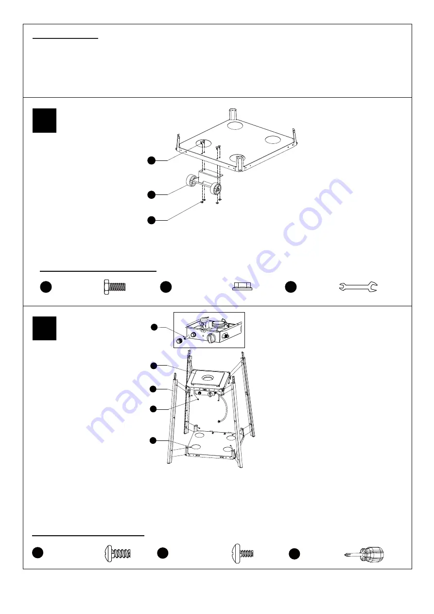
2
Hardware Used
EE
FF
II
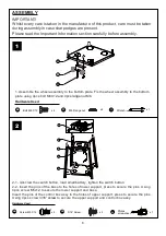
1. Assemble the wheel assembly to the bottom plate. Fix the wheel assembly to the bottom
plate using 4pcs bolt M6X12 and 4pcs
lange nut
M6.
x 4
x 4
Wrench
x 1
Bolt M6 X 12
M6 Flange nut
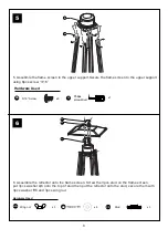
2-1
.
Unscrew the switch button, load small battery, tighten the switch button.
2-2. Insert the pins of the base to the holes of lower support, press to secure the pins. Using
4pcs screw M5x12 to secure the lower support and base.
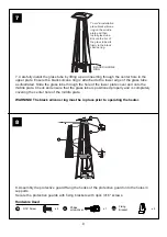
Insert the pins of the control box assy to the holes of upper support, press to secure the pins.
Using 4pcs screw
3/16” screw
to secure the upper support and control box assy.
Hardware Used
GG
JJ
x 4
Philips
screwdriver
x 1
Screw M5 X 12
DD
x 4
3/16” Screw
M
EE
FF
J
K
DD
GG
OO
AA Battery (1.5 V)


